Isuzu KB P190. Manual — part 1337
8A-410 ELECTRICAL-BODY AND CHASSIS
REMOVAL AND INSTALLATION
This illustration is based on 2 doors and RHD
RTW780SH002601
DRIVER’S SEAT SIDE POWER WINDOW
& DOOR LOCK SWITCH
Removal
1. Disconnect the battery ground cable.
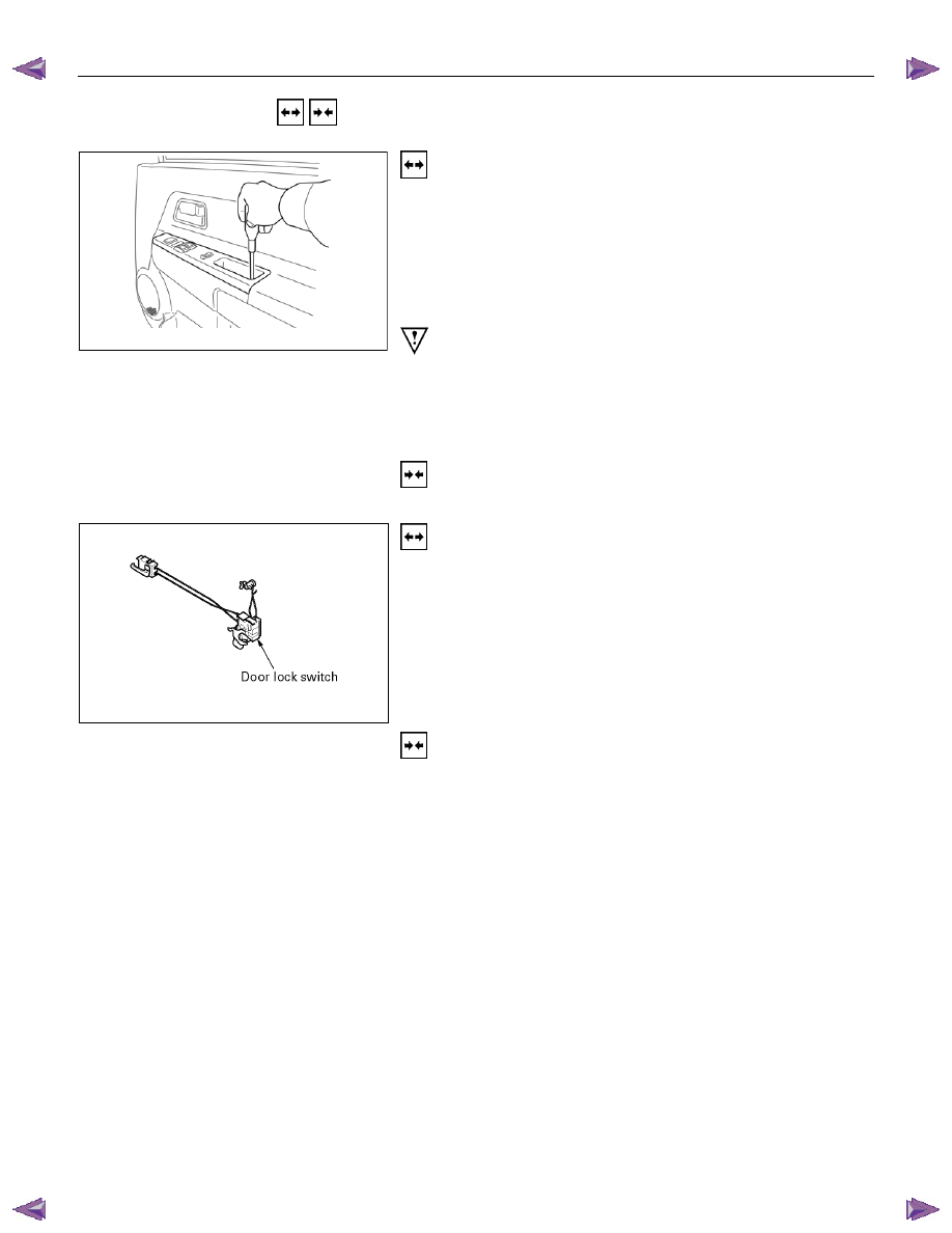
2. Removes the screw in pull cup with the screwdriver.
3. Remove the switch bezel by pushing the spring with the tip
of a screwdriver.
4. Disconnect the connector.
ATTENTION:
When removing a switch bezel lift from the front of the
bezel.
It follows the front with the screwdriver.
The clip can break when lifting from the rear of the bezel.
Installation
To install, follow the removal steps in the reverse order.
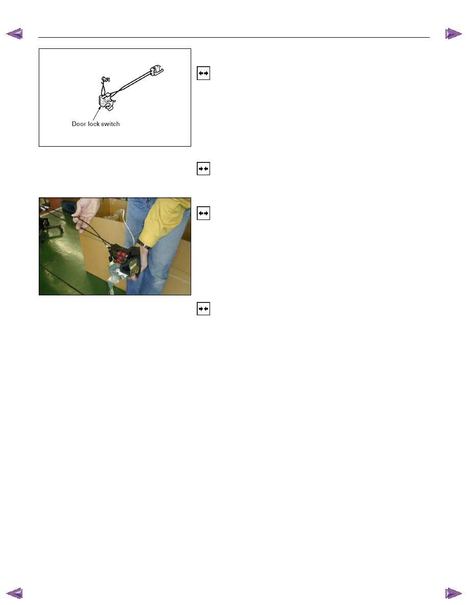
DRIVER’S SIDE DOOR LOCK SWITCH
Removal
1. Door Lock ASM
• Refer to the removal steps of the DOORS in section 10
“BODY”.
2. Door Lock Switch
Installation
To install, follow the removal steps in the reverse order.
ELECTRICAL-BODY AND CHASSIS 8A-411
FRT PASSENGER’S SIDE DOOR LOCK
ACTUATOR
Removal
1. Door Lock ASM
• Refer to the removal steps of the DOORS in Section 10
“BODY”.
2. Door Lock Actuator
• Remove the door lock switch fixing bolts.
• Disconnect the door lock link rod.
• Disconnect the door lock switch connector.
Installation
To install, follow the removal steps in the reverse order.
RR DOOR LOCK ACTUATOR-LH & RH
Removal
1. Door Lock ASM
• Refer to the removal steps of the DOORS in section 10
“BODY”.
2. Door Lock Actuator
• Remove the actuator fixing bolts.
• Disconnect the door lock link rod.
• Disconnect the actuator connector.
Installation
To install, follow the removal steps in the reverse order.
8A-412 ELECTRICAL-BODY AND CHASSIS
INSPECTION AND REPAIR
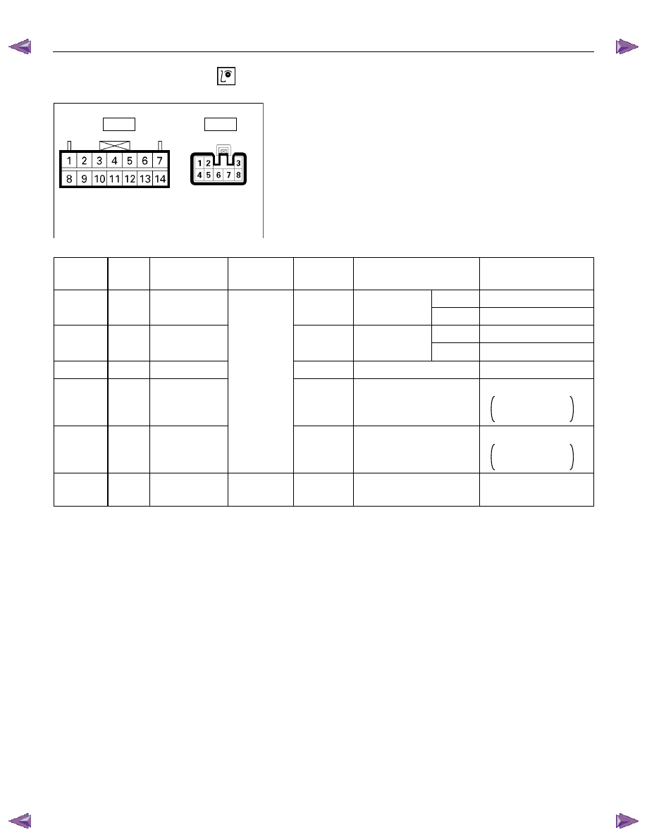
Harness side
D20
D5
Driver’s Side Power Window & Door Lock
Switch
1. Harness Side Connector Circuit
Check voltage and continuity between the switch harness
side connector terminals as shown in the following table.
Terminal
No.
Wire
color
Connecting to Check item
Connectin
g terminal
Check condition
Standard
Door lock SW
Driver’s
Lock Continuity
(Lock)
side door
Unlock No
continuity
Door lock SW
Driver’s
Lock No
continuity
(Unlock)
side door
Unlock Continuity
3 (D5)
L/R
Ground
Continuity
3-Ground
- Continuity
4 (D5)
L/R
Door lock
actuator (Lock)
(Resistance)
4-5
-
Continuity
There is some
resistance
5 (D5)
L
Door lock
actuator
(Unlock)
5-4
-
Continuity
There is some
resistance
1 (D5)
LG/W
Fuse
C21 (20A)
Voltage 1-
Ground
-
Battery voltage
(Approx. 12V)
14-Ground
L/R
14 (D20)
13-Ground
L/Y
13 (D20)
ELECTRICAL-BODY AND CHASSIS 8A-413
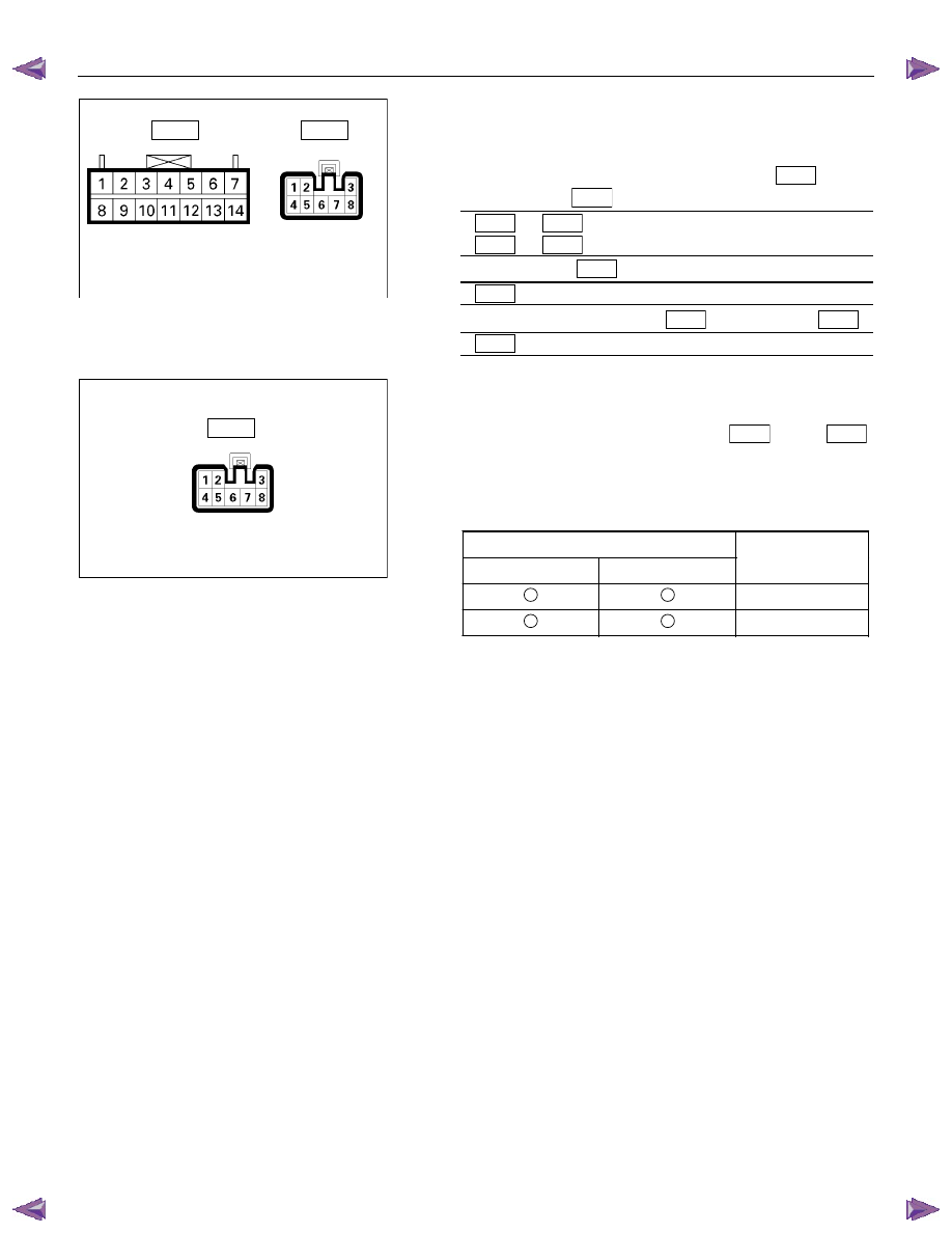
Harness side
D20
D5
2. Switch Side Connector Circuit
Remove the switch connector, and check continuity and
voltage between the switch connector terminals.
(Connect the (+) terminal of the battery to 1
D5
and the
(-) terminal to 3
D5
.)
3
D5
- 4
D5
. . . . .. Continuity
3
D5
- 5
D5
. . . . .. Continuity
(Then, ground 3
D5
.)
4
D5
. . .. Current flow for approx. 1 second
(Disconnect the ground of 14
D20
, and ground 13
D20
.)
5
D5
. . .. Current flow for approx. 1 second
Harness side
D5
3. Door Lock Operation Test
After confirming that there is continuity between the switch
harness side connector terminals 4
D5
and 5
D5
,
apply the battery voltage to each of the terminals to conduct
the operation test.
When the door lock will not operate, check the door lock
actuator for any trouble.
Connecting terminals
5 (L)
4 (L/R)
+
-
Unlock
-
+
Lock
Operation
Нет комментариевНе стесняйтесь поделиться с нами вашим ценным мнением.
Текст