Isuzu KB P190. Manual — part 554
6E–46
ENGINE DRIVEABILITY AND EMISSIONS
Reference Wave Form
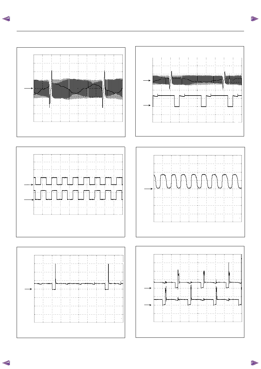
Crankshaft Position (CKP) Sensor Reference Wave Form
0V
Measurement Terminal: J1-21(+) J1-6(-)
Measurement Scale: 10V/div 5ms/div
Measurement Condition: Approximately 2000rpm
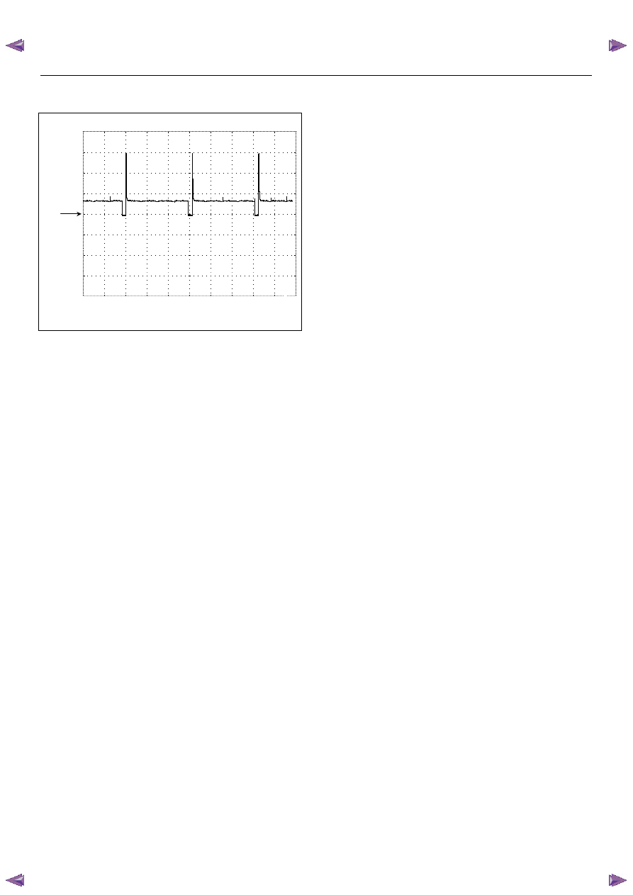
Ve h ic le S p e ed S e n so r (V S S ) R e fe re n c e W a ve F o rm
C H 1
0 V
C H 2
0 V
M easurem ent Term inal: CH1: ECM J2-23(+) / CH2: VSS 3(+) GND(-)
Measurem ent Scale: CH1: 10V/div / CH2: 10V/div 50m s/div
Measurem ent Condition: Approxim ately 20km /h
Note: The vehicle is w ithout imm obilizer system,
CH1 signal is same as CH2.
Injector Control Signal Reference Wave Form
0V
Measurement Terminal: J1-9(+) (No.1 Cylinder) GND(-)
Measurement Scale: 20V/div 5ms/div
Measurement Condition: Approximately 2000rpm
Crankshaft Position (CKP) Sensor & Tacho Output Signal
Reference W ave Form
CH1
0V
CH2
0V
Measurement Terminal: CH1: J1-21(+) / CH2: J2-25(+) GND(-)
Measurem ent Scale: CH1: 2V/div / CH2: 10V/div 5m s/div
Measurem ent Condition: Approxim ately 2000rpm
Heated Oxygen Sensor (HO2S) Reference Wave Form
0V
Measurement Terminal: J2-21(+) GND(-)
Measurement Scale: 500mV/div 500ms/div
Measurement Condition: Approximately 2000rpm in Closed Loop
Ignition Coil Control Signal Reference Wave Form
CH1
0V
CH2
0V
Measurement Terminal: CH1: J1-19(+) / CH2: J1-18(+) GND(-)
Measurement Scale: CH1: 20V/div / CH2: 20V/div 10ms
Measurement Condition: Approximately 2000rpm
ENGINE DRIVEABILITY AND EMISSIONS
6E–47
EVAP Canister Purge Solenoid Reference Wave Form
0V
Measurement Terminal: J1-5(+) GND(-)
Measurement Scale: 20V/div 20ms/div
Frequency: Approximately 16Hz
6E–48
ENGINE DRIVEABILITY AND EMISSIONS
GENERAL DESCRIPTION FOR ECM AND
SENSORS
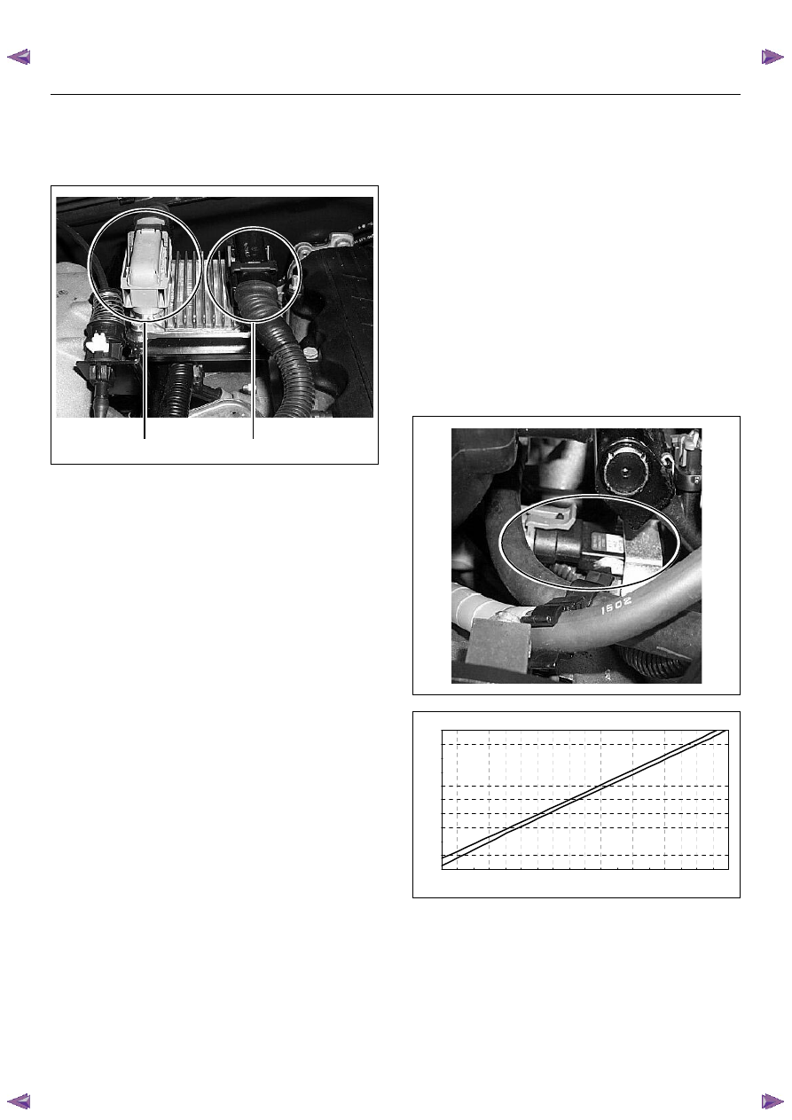
Engine Control Module (ECM)
The engine control module (ECM) is located on the
intake manifold. The ECM controls the following.
• Fuel metering system
• Ignition timing
• On-board diagnostics for electrical functions.
The ECM constantly observes the information from vari-
ous sensors. The ECM controls the systems that affect
vehicle performance. And it performs the diagnostic
function of the system.
The function can recognize operational problems, and
warn to the driver through the check engine lamp, and
store diagnostic trouble code (DTC). DTCs identify the
problem areas to aid the technician in marking repairs.
The input / output devices in the ECM include analog to
digital converts, signal buffers, counters and drivers.
The ECM controls most components with electronic
switches which complete a ground circuit when turned
on.
Inputs (Operating condition read):
• Battery voltage
• Electrical ignition
• Exhaust oxygen content
• Intake manifold pressure
• Intake air temperature
• Engine coolant temperature
• Crankshaft position
• Knock signal
• Throttle position
• Vehicle speed
• Power steering pressure
• Air conditioning request on or off
Outputs (Systems controlled):
• Ignition control
• Fuel control
• Idle air control
• Fuel pump
• EVAP canister purge
• Air conditioning
• Diagnostics functions
Manifold Absolute Pressure (MAP) Sensor
The MAP sensor is a strain gage. A pressure strains the
resistance on the silicon base. At that time the
resistance value changes. And it changes voltage. In
other words it measures a pressure value. It is installed
to the intake manifold. Output voltage of the MAP
sensor is low as pressure is low.
(1) J1 Port
(2) J2 Port
1
2
C harac t eris t ic of MAP Sens or -R ef erenc e-
0
0.5
1
1.5
2
2.5
3
3.5
4
4.5
5
15
20
25
30
35
40
45
50
55
60
65
70
75
80
85
90
95
100
105
Mani fol d A bs ol ute P res s ure (K P a) (T ec h2 Readi ng)
O
ut
put
Vol
tage (
V
)
ENGINE DRIVEABILITY AND EMISSIONS
6E–49
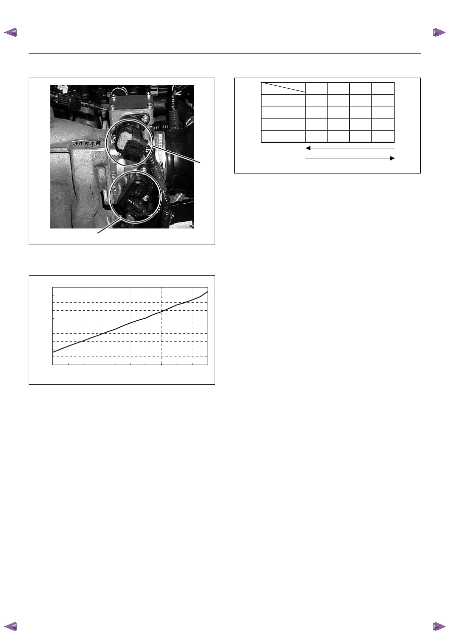
Throttle Position Sensor (TPS)
The TPS is a potentiometer connected to throttle shaft
on the throttle body.
The engine control module (ECM) monitors the voltage
on the signal line and calculates throttle position. As the
throttle valve angle is changed when accelerator pedal
moved. The TPS signal also changed at a moved
throttle valve. As the throttle valve opens, the output
increases so that the output voltage should be high.
The throttle body has a throttle plate to control the
amount of the air delivered to the engine.
Engine coolant is directed through a coolant cavity in
the throttle body to warm the throttle valve and to
prevent icing.
Idle Air Control (IAC) Valve
The idle air control valve (IAC) valve is two directional
and gives 2-way control. With power supply to the coils
controlled steps by the engine control module (ECM),
the IAC valve's pintle is moved to adjust idle speed,
raising it for fast idle when cold or there is extra load
from the air conditioning or power steering.
By moving the pintle in (to decrease air flow) or out (to
increase air flow), a controlled amount of the air can
move around the throttle plate. If the engine speed is
too low, the engine control module (ECM) will retract the
IAC pintle, resulting in more air moving past the throttle
plate to increase the engine speed.
If the engine speed is too high, the engine control
module (ECM) will extend the IAC pintle, allowing less
air to move past the throttle plate, decreasing the
engine speed.
The IAC pintle valve moves in small step called counts.
During idle, the proper position of the IAC pintle is
calculated by the engine control module (ECM) based
on battery voltage, coolant temperature, engine load,
and engine speed.
If the engine speed drops below a specified value, and
the throttle plate is closed, the engine control module
(ECM) senses a near-stall condition. The engine control
module (ECM) will then calculate a new IAC pintle valve
position to prevent stalls.
If the IAC valve is disconnected and reconnected with
the engine running, the idle speed will be wrong. In this
case, the IAC must be reset. The IAC resets when the
key is cycled “On” then “Off”. When servicing the IAC, it
should only be disconnected or connected with the
ignition “Off”.
The position of the IAC pintle valve affects engine start-
up and the idle characteristic of the vehicle.
If the IAC pintle is fully open, too much air will be
allowed into the manifold. This results in high idle
speed, along with possible hard starting and lean air/
fuel ratio.
(1) Throttle Position Sensor
(2) Idle Air Control (IAC) Valve
1
2
C haracterist ic of TPS -R ef erence-
0
0.5
1
1.5
2
2.5
3
3.5
4
4.5
5
0
10
20
30
40
50
60
70
80
90
100
Throt tle Angle (%) (Tech2 R eading)
O
ut
put
Vol
tage (
V
)
Step
Coil
A
B
C
D
Coil A High
(ECM J1-28)
On
On
Coil A Low
(ECM J1-30)
On
On
Coil B High
(ECM J1-13)
On
On
Coil B Low
(ECM J1-29)
On
On
(IAC Valve Close Direction)
(IAC Valve O pen Direction)
Нет комментариевНе стесняйтесь поделиться с нами вашим ценным мнением.
Текст