Isuzu KB P190. Manual — part 553
6E–42
ENGINE DRIVEABILITY AND EMISSIONS
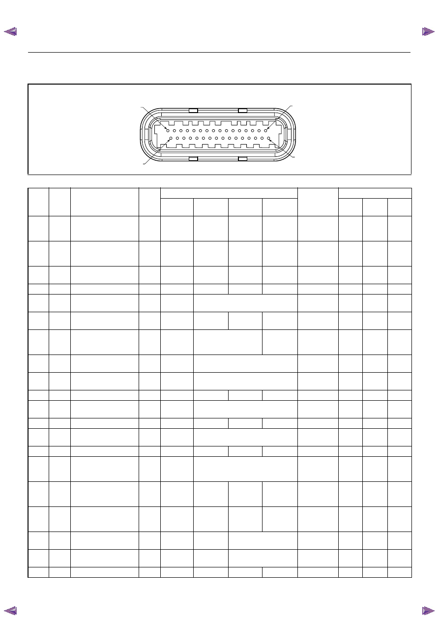
ECM CONNECTOR PIN ASSIGNMENT & OUTPUT SIGNAL
Connector J1 Port: View Looking Into ECM Case
1
17
16
32
PIN16
PIN1
PIN17
PIN32
Pin
No.
B/
Box
No.
Pin Function
Wire
Color
Signal or Continuity
ECM
Connection
Tester Position
Key SW
Off
Key SW
On
Engine
Idle
Engine
2000rpm
Range
(+)
(-)
J1-1
J1-1
Ground
BLK/
WHT
Continuity
with
ground
-
-
-
Disconnect
Ω
J1-1
GND
J1-2
J1-2
Ground
BLK/
WHT
Continuity
with
ground
-
-
-
Disconnect
Ω
J1-2
GND
J1-3
J1-3
Knock Sensor Signal
YEL
Less than
1V
-
-
-
-
-
-
-
J1-4
J1-4
No Connection
-
-
-
-
-
-
-
-
-
J1-5
J1-5
Canister Purge
Solenoid Valve
RED/
YEL
Less than
1V
Wave form G or 12-14V
Connect
DC V
J1-5
GND
J1-6
J1-6
Crankshaft Position
(CKP) Sensor (Ground)
RED Approx.
0.58kΩ
-
-
-
Disconnect
Ω
J1-6
J1-21
J1-7
J1-7
Throttle Position
Sensor (TPS) Output
Signal
BLU
Less than
1V
Approx 0.7V
Approx
0.8V
Connect
DC V
J1-7
J1-32
J1-8
J1-8
No. 3 Injector
GRN/
BLK
Less than
1V
Wave form E or 12-14V
Connect
DC V
J1-8
GND
J1-9
J1-9
No. 1 Injector
GRN/
WHT
Less than
1V
Wave form E or 12-14V
Connect
DC V
J1-9
GND
J1-10
J1-10
No Connection
-
-
-
-
-
-
-
-
-
J1-11
J1-11
No. 4 Injector
GRN
Less than
1V
Wave form E or 12-14V
Connect
DC V
J1-11
GND
J1-12
J1-12
No Connection
-
-
-
-
-
-
-
-
-
J1-13
J1-13
Idle Air Control Valve
(IACV) Coil B High
BLU/
RED
Less than
1V
Less than 1V / 10-14V
Connect
DC V
J1-13
GND
J1-14
J1-14
No Connection
-
-
-
-
-
-
-
-
-
J1-15
J1-15
Throttle Position
Sensor (TPS) Power
Supply
RED
Less than
1V
Approx. 5V
Connect
DC V
J1-15
J1-32
J1-16
J1-16
MAP Sensor Ground
GRN
Continuity
with
ground
-
-
-
Connect
Ω
J1-16
GND
J1-17
J1-17
Ground
BLK/
WHT
Continuity
with
ground
-
-
-
Connect
Ω
J1-17
GND
J1-18
J1-18
Coil Module 2 (No. 2 &
3 Cylinder)
BLU -
-
Wave
form
F
-
-
-
-
J1-19
J1-19
Coil Module 1 (No. 1 &
4 Cylinder)
GRN
-
-
Wave form F
-
-
-
-
J1-20
J1-20
No Connection
-
-
-
-
-
-
-
-
-

ENGINE DRIVEABILITY AND EMISSIONS
6E–43
J1-21
J1-21
Crankshaft Position
(CKP) Sensor Signal
WHT -
-
Wave
form
or approx.
3.7V
Wave form
A or
approx.
7.8V
Connect
AC V
J1-21
J1-6
J1-22
J1-22
No.2 Injector
GRN/
WHT
Less than
1V
Wave form E or 12-14V
Connect
DC V
J1-22
GND
J1-23
J1-23
No Connection
-
-
-
-
-
-
-
-
-
J1-24
J1-24
MAP Sensor Signal
GRY
Less than
1V
Approx.
4.8V
Approx.
1.3V
Approx.
0.9V
Connect
DC V
J1-24
J1-16
J1-25
J1-25
No Connection
-
-
-
-
-
-
-
-
-
J1-26
J1-26
No Connection
-
-
-
-
-
-
-
J1-26
-
J1-27
J1-27
Engine Coolant Temp.
(ECT) Sensor Signal
GRY
Less than
1V
20℃: Approx. 2.4V / 40℃: Approx. 1.4V or
4.1V / 60 ℃ : Approx. 3.3V / 80 ℃ : Approx.
2.5V
Connect
DC V
J1-27
J1-32
J1-28
J1-28
Idle Air Control Valve
(IACV) Coil A High
BLU
Less than
1V
Less than 1V / 10-14V
Connect
DC V
J1-28
GND
J1-29
J1-29
Idle Air Control Valve
(IACV) Coil B Low
BLU/
BLK
Less than
1V
Less than 1V / 10-14V
Connect
DC V
J1-29
GND
J1-30
J1-30
Idle Air Control Valve
(IACV) Coil A Low
BLU/
WHT
Less than
1V
Less than 1V / 10-14V
Connect
DC V
J1-30
GND
J1-31
J1-31
MAP Sensor Power
Supply
RED
Less than
1V
Approx.. 5V
Connect
DC V
J1-31
J1-16
J1-32
J1-32
ECT Sensor, Knock
Sensor, Throttle
Position Sensor Ground
GRN
Continuity
with
ground
-
-
-
Connect
Ω
J1-32
GND
Pin
No.
B/
Box
No.
Pin Function
Wire
Color
Signal or Continuity
ECM
Connection
Tester Position
Key SW
Off
Key SW
On
Engine
Idle
Engine
2000rpm
Range
(+)
(-)
6E–44
ENGINE DRIVEABILITY AND EMISSIONS
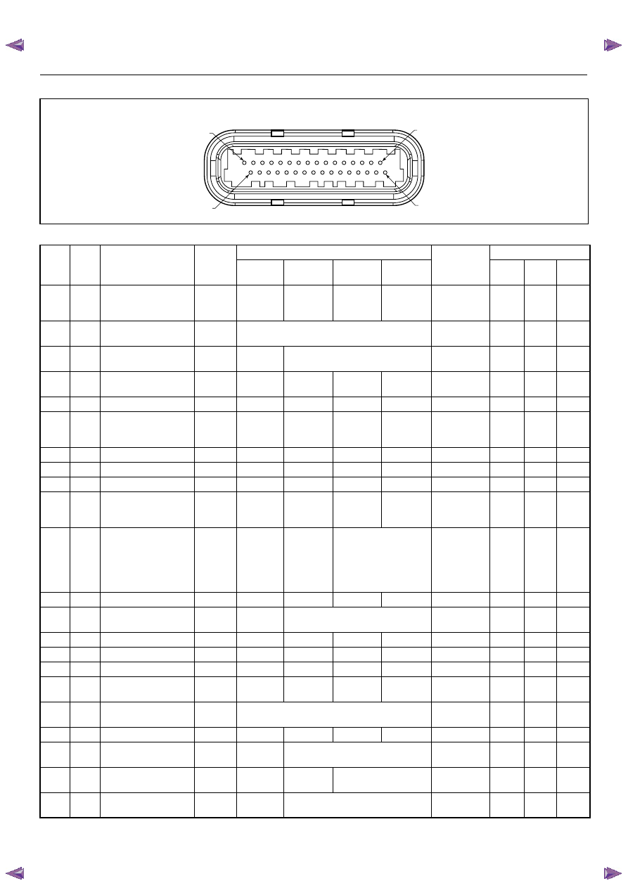
Connector J2 Port: View Looking Into ECM Case
1
17
16
32
PIN32
PIN1
PIN17
PIN16
Pin
No.
B/
Box
No.
Pin Function
Wire
Color
Signal or Continuity
ECM
Connection
Tester Position
Key SW
Off
Key SW
On
Engine
Idle
Engine
2000rpm
Range
(+)
(-)
J2-1
J2-1
Intake Air Temp. (IAT)
Sensor Ground
GRN
Continuity
with
ground
-
-
-
Disconnect
Ω
J2-1
GND
J2-2
J2-2
Battery Power Supply
RED/
WHT
10-14V
Connect
DC V
J2-2
GND
J2-3
J2-3
Ignition Power Supply
BLU/
YEL
Less than
1V
10-14V
Connect
DC V
J2-3
GND
J2-4
J2-4
To Data Link
Connector No. 6
BLU -
-
-
-
-
-
-
-
J2-5
J2-5
No Connection
-
-
-
-
-
-
-
-
-
J2-6
J2-6
Oxygen Sensor
(Ground)
PNK
Continuity
with
ground
-
-
-
Connect
Ω
J2-6
GND
J2-7
J2-7
No Connection
-
-
-
-
-
-
-
-
-
J2-8
J2-8
No Connection
-
-
-
-
-
-
-
-
-
J2-9
J2-9
No Connection
-
-
-
-
-
-
-
-
-
J2-10
J2-10
CO Adjust Signal
(W/O Catalystic
Converter)
YEL
-
-
-
-
-
-
-
-
J2-11
J2-11
Fuel Pump Relay
GRN/
WHT
10-14V
While relay
is activated;
10-14V
Relay is not
activated;
Less than
1V
10-14V
Connect
DC V
J2-11
GND
J2-12
J2-12
No Connection
-
-
-
-
-
-
-
-
-
J2-13
J2-13
A/C Compressor
Relay
GRY/
RED
Less than
1V
A/C comp. is operated: Less than 1V
A/C comp. is not operated: 10-14V
Connect
DC V
J2-13
GND
J2-14
J2-14
No Connection
-
-
-
-
-
-
-
-
-
J2-15
J2-15
No Connection
-
-
-
-
-
-
-
-
-
J2-16
J2-16
No Connection
-
-
-
-
-
-
-
-
-
J2-17
J2-17
CO Adjust (W/O
Catalystic Converter)
RED
-
-
-
-
-
-
-
-
J2-18
J2-18
Battery Power Supply
RED/
WHT
10-14V
Connect
DC V
J2-18
GND
J2-19
J2-19
No Connection
-
-
-
-
-
-
-
-
-
J2-20
J2-20
Power Steering
Pressure Switch
GRN/
YEL
Less than
1V
Pressure switch is turned on: Less than 1V
Pressure switch is turned off: 10-14V
Connect
DC V
J2-20
GND
J2-21
J2-21
Oxygen Sensor
BLU
Less than
1V
Approx.
0.4V
Wave form D or 0.1 -
0.9V
Connect
DC V
J2-21
J2-6
J2-22
J2-22
Intake Air Temp. (IAT)
Sensor (Signal)
YEL/
GRN
Less than
1V
20℃: Approx. 2.9V / 40℃: Approx. 1.8V V
/ 60 ℃ : Approx. 1.1V / 80 ℃ : Approx. 0.6V
Connect
DC V
J2-22
33
ENGINE DRIVEABILITY AND EMISSIONS
6E–45
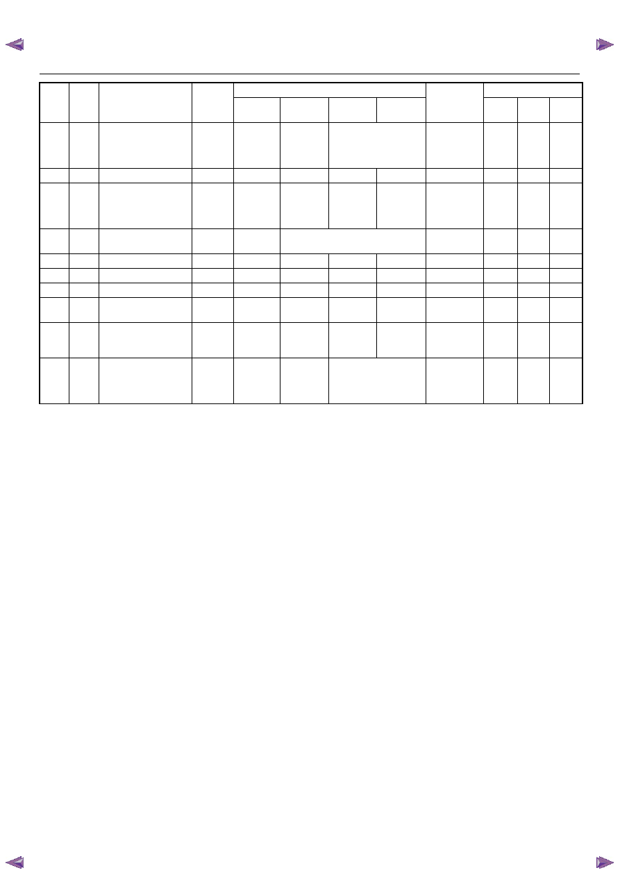
J2-23
J2-23
Vehicle Speed Sensor
(VSS) Signal
(Immobilizer Control
Unit Terminal B8)
WHT
-
-
Wave form C or Approx.
6.5V at 20km/h
Connect
AC V
J2-23
GND
J2-24
J2-24
No Connection
-
-
-
-
-
-
-
-
-
J2-25
J2-25
Tachometer Output
Signal
BLK/
RED
-
-
Wave form
Wave form
B or
Approx.
4.5V
Connect
AC V
J2-25
GND
J2-26
J2-26
Thermo Relay
GRN/
BLK
Less than
1V
A/C request is activated: 10-14V
A/C request is not activated: Less than 1V
Connect
DC V
J2-26
GND
J2-27
J2-27
No Connection
-
-
-
-
-
-
-
-
-
J2-28
J2-28
No Connection
-
-
-
-
-
-
-
-
-
J2-29
J2-29
No Connection
-
-
-
-
-
-
-
-
-
J2-30
J2-30
To Data Link
Connector No. 2
GRN
-
-
-
-
-
-
-
-
J2-31
J2-31
Oxygen Sensor Heater
BLU/
WHT
Continuity
with
ground
-
Wave
Form
Wave
Form D
Connect
Ω
J2-31
GND
J2-32
J2-32
Check Engine Lamp
(Immobilizer Control
Unit Terminal B7)
BRN/
YEL
Less than
1V
Less than
1V
Lamp is turned on: Less
than 1V
Lamp is turned off: 10-
14V
Connect
DC V
J2-32
GND
Pin
No.
B/
Box
No.
Pin Function
Wire
Color
Signal or Continuity
ECM
Connection
Tester Position
Key SW
Off
Key SW
On
Engine
Idle
Engine
2000rpm
Range
(+)
(-)
Нет комментариевНе стесняйтесь поделиться с нами вашим ценным мнением.
Текст