Isuzu KB P190. Manual — part 168

BRAKE CONTROL SYSTEM 5A-79
Step Action Value(s) Yes
No
6
1. Remove the G sensor.
2. Reconnect G sensor and EHCU
3. Install the Tech 2.
4. Ignition "ON", engine "OFF".
5. Observe the G sensor reading on Tech 2.
If G sensor inclines, reading voltage will change.
Is the reading voltage between specified values?
1.0 - 4.0V
Go to Step 7
Go to Step 8
7
1. Ignition "OFF".
2. Install the G sensor.
3. Install the Tech 2.
4. Ignition "ON", engine "OFF".
5. Select "Display DTCs" with the Tech 2.
Are any DTCs stored?
-
Go to Step 8
Verify repair
8
1. Replace G sensor.
2. Select "Display DTCs" with the Tech 2.
Note: Perform the various tests (actuator test, test
run, brake test, etc.) then observe the DTC with a
Tech 2.
Are any DTCs stored?
-
Go to Step 9
Verify repair
9 Replace
EHCU.
Note: Check the EHCU type for specification, when
the EHCU is replaced.
(Specification ; 2WD model or 4WD model)
Is the action complete?
-
Verify repair
-

5A-80 BRAKE CONTROL SYSTEM
DTC C0277 (Flash Code 77) System Voltage Low
DTC C0278 (Flash Code 78) System Voltage High
RTW75ALF000301
Step Action Value(s) Yes
No
1
Were the steps of the “Basic Diagnostic Flow Chart”
performed?
-
Go to Step 2
Go to Basic
Diagnostic
Flow Chart
2
1. Check for a poor connection at EHCU
2. If a problem is found, repair as necessary.
Was a problem found?
-
Verify repair
Go to Step 3
3
1. Ignition “OFF”, disconnect EHCU.
2. Ignition “ON”, engine “OFF”.
3. Check the supply voltage to EHCU.
Is the value normal?
Battery
Voltage
Go to Step 5
Go to Step 4
4
Repair or replace the power supply circuit.
Is the action complete?
-
Verify repair
-

BRAKE CONTROL SYSTEM 5A-81
Step Action Value(s) Yes
No
5
1. Check the power supply circuit.
(Check circuit for an open, short to ground, or short
to voltage.)
2. If a problem is found, repair as necessary.
Was a problem found?
-
Verify repair
Go to Step 6
6
1. Ignition “ON”, engine “OFF”.
2. Select “Display DTCs” with the Tech 2.
Note: Perform the various tests (actuator test, test
run, brake test, etc.) then observe the DTC with a
Tech 2.
Are any DTCs stored?
-
Go to Step 7
Verify repair
7 Replace
EHCU.
Note: Check the EHCU type for specification, when
the EHCU is replaced.
(Specification ; 2WD model or 4WD model)
Is the action complete?
-
Verify repair
-
5A-82 BRAKE CONTROL SYSTEM
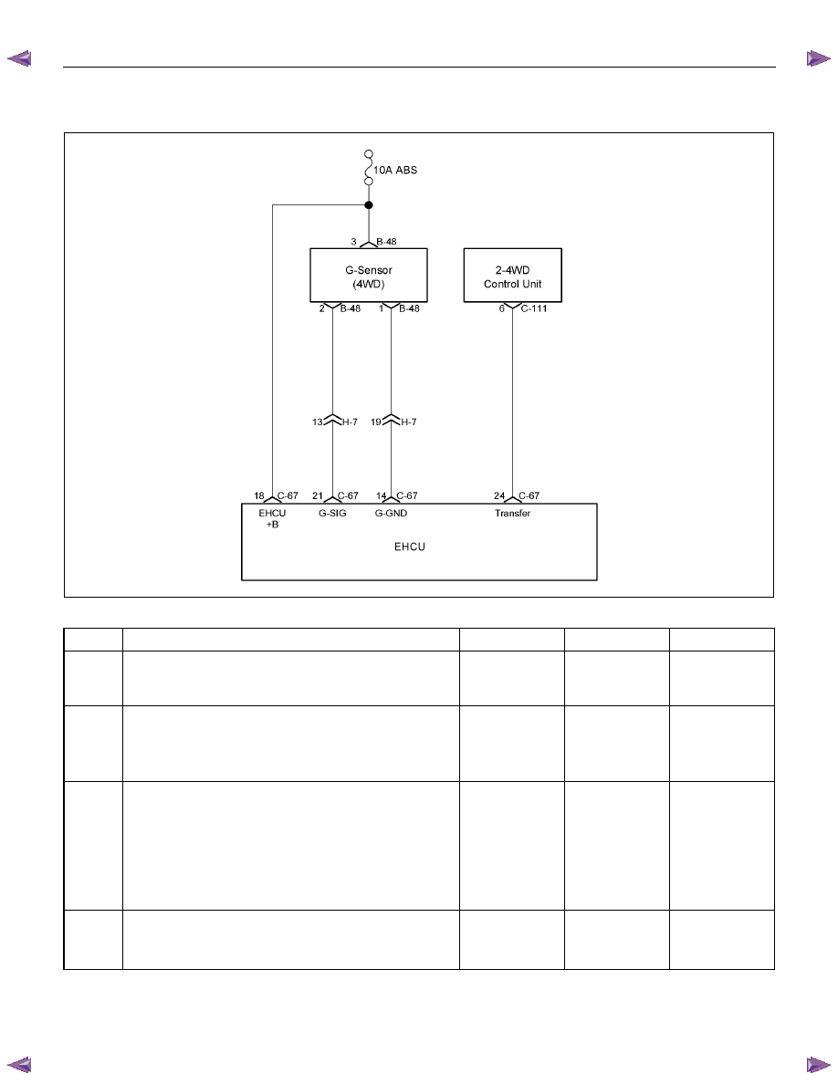
DTC C0282 (Flash Code 82) 4 Wheel Drive State Input Signal Failure
RTW75AMF001501
Step Action Value(s) Yes
No
1
Were the steps of the “Basic Diagnostic Flow Chart”
performed?
-
Go to Step 2
Go to Basic
Diagnostic
Flow Chart
2
1. Check for a poor connection at EHCU and 2-4WD
control unit.
2. If a problem is found, repair as necessary.
Was a problem found?
-
Verify repair
Go to Step 3
3
1. Ignition “OFF”, disconnect the EHCU and 2-4WD
control unit.
2. Check the circuit between EHCU and 2-4WD
control unit. (Circuit for an open, short to ground, or
short to voltage.)
3. If a problem is found, repair as necessary.
Was a problem found?
-
Verify repair
Go to Step 4
4
1. Check the 2-4WD Control system.
2. If a problem is found, repair as necessary.
Was a problem found?
-
Verify repair
Go to Step 5
Нет комментариевНе стесняйтесь поделиться с нами вашим ценным мнением.
Текст