Isuzu KB P190. Manual — part 169

BRAKE CONTROL SYSTEM 5A-83
Step Action Value(s) Yes
No
5
1.
Ignition
"OFF".
2. Connect 2-4WD control unit.
3. Disconnect EHCU.
4. Ignition "ON," engine "OFF."
5. Install the high impedance digital multimeter.
6. Check the transfer (2-4WD control unit) signal
value. (Battery voltage is more than 10V.)
Was the value normal?
Transfer 2WD
Mode: 8.3Hz
(±15%)
Transfer 4WD
Mode: 4.2Hz
(±15%)
Go to Step 7
Go to Step 6
6
Replace 2-4WD control unit.
Is the action complete?
-
Go to Step 7
-
7
1. Ignition “ON”, engine “OFF”.
2. Select “Display DTCs” with the Tech 2.
Note: Perform the various tests (actuator test, test
run, brake test, etc.) then observe the DTC with a
Tech 2.
Are any DTCs stored?
-
Go to Step 8
Verify repair
8 Replace
EHCU.
Note: Check the EHCU type for specification, when
the EHCU is replaced.
(Specification ; 2WD model or 4WD model)
Is the action complete?
-
Verify repair
-

5A-84 BRAKE CONTROL SYSTEM
DTC C0285 (Flash Code 85) Control Module Vehicle Options Incorrect
RTW75AMF001501
Step Action Value(s)
Yes
No
1
Were the steps of the “Basic Diagnostic Flow Chart”
performed?
-
Go to Step 2
Go to Basic
Diagnostic
Flow Chart
2
1.
Ignition
“OFF”.
2. Check for vehicle type and EHCU type.
(Vehicle type : 2WD or 4WD)
3. Check that the EHCU type is the same as the
vehicle type.
If the EHCU type differs from the vehicle type,
EHCU is replaced.
Note: Check the EHCU type for specification, when
the EHCU is replaced.
(Specification ; 2WD model or 4WD model)
Is the action complete?
-
Go to Step 3
-
3
1. Check for vehicle type. (Vehicle type : 2WD or
4WD)
Is vehicle type 2WD?
-
Go to Step 4
Go to Step 5

BRAKE CONTROL SYSTEM 5A-85
Step Action Value(s)
Yes
No
4
1.
Ignition
"OFF".
2. Check for a poor condition at the EHCU harness
connector.
3. Check the EHCU circuit for an open, short to
ground, or short to voltage. Also, check the EHCU
ignition feed circuit for an open or short to ground
and the EHCU ground circuit for an open or short to
voltage.
4. If a problem is found, repair as necessary.
Was a problem found?
-
Verify repair
Go to Step 9
5
1. Ignition "OFF", disconnect the EHCU and G sensor.
2. Check the circuit between EHCU and G sensor.
(short to ground, or short to voltage.)
3. If a problem is found, repair as necessary.
Was a problem found?
-
Verify repair
Go to Step 6
Go to Step 6
6
1. Remove the G sensor.
2. Reconnect G sensor and EHCU
3. Install the Tech 2.
4. Ignition "ON", engine "OFF".
5. Observe the G sensor reading on Tech 2.
If G sensor inclines, reading voltage will change.
Is the reading voltage between specified values?
1.0 – 4.0 V
Go to Step 7
Go to Step 8
7
1.
Ignition
"OFF".
2. Install the G sensor.
3. Install the Tech 2.
4. Ignition "ON", engine "OFF".
5. Select "Display DTCs" with the Tech 2.
Are any DTCs stored?
-
Go to Step 8
Verify repair
8
1. Replace G sensor.
2. Select "Display DTCs" with the Tech 2.
Note: Perform the various tests (actuator test, test
run, brake test, etc.) then observe the DTC with a
Tech 2.
Are any DTCs stored?
-
Go to Step 9
Verify repair
9 Replace
EHCU.
Note: Check the EHCU type for specification, when
the EHCU is replaced.
(Specification ; 2WD model or 4WD model)
Is the action complete?
-
Verify repair
-
5A-86 BRAKE CONTROL SYSTEM
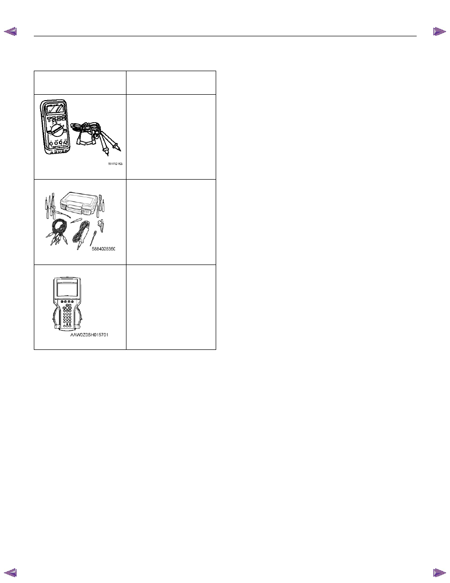
Special Tools
ILLUSTRATION
TOOL NO.
TOOL NAME
5–8840–0366–0
High impedance
multimeter
5–8840–2835–0
Connector Test Adapter
Kit (With Test Lamp)
Tech2 Kit
Нет комментариевНе стесняйтесь поделиться с нами вашим ценным мнением.
Текст