Isuzu KB P190. Manual — part 69
POWER-ASSISTED STEERING SYSTEM 3B-15
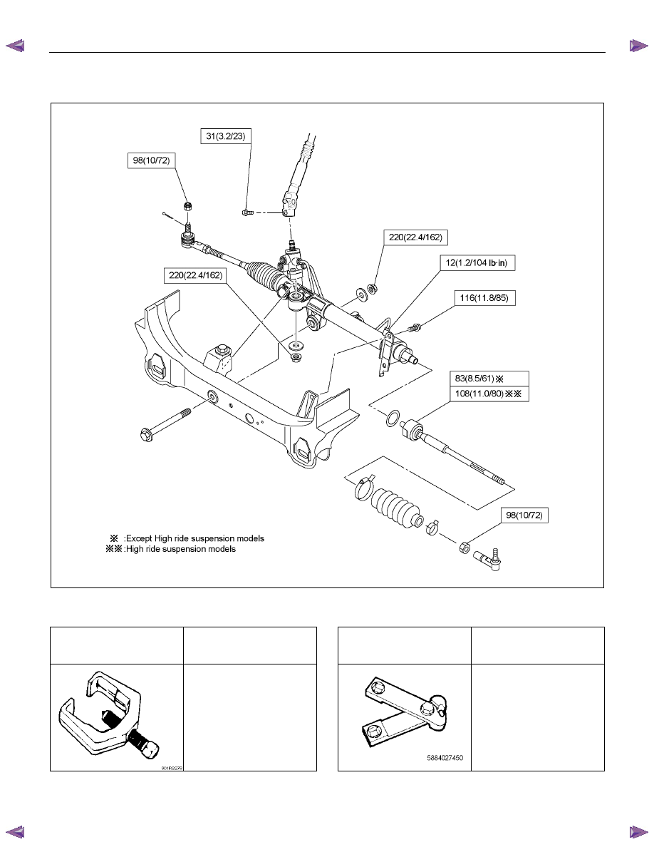
3. Install tie-rod assembly with tab washer, then tighten
to specified torque.
For 4
×2 except High ride suspension models;
Torque: 83 N
⋅⋅⋅⋅m (8.5 kgf⋅⋅⋅⋅m/61 lb⋅⋅⋅⋅ft)
For 4
×4 and 4×2 High ride suspension models;
Torque: 108 N
⋅⋅⋅⋅m (11.0 kgf⋅⋅⋅⋅m/80 lb⋅⋅⋅⋅ft)
After tightening, bend tab washer against width
across flat of inner ball joint.
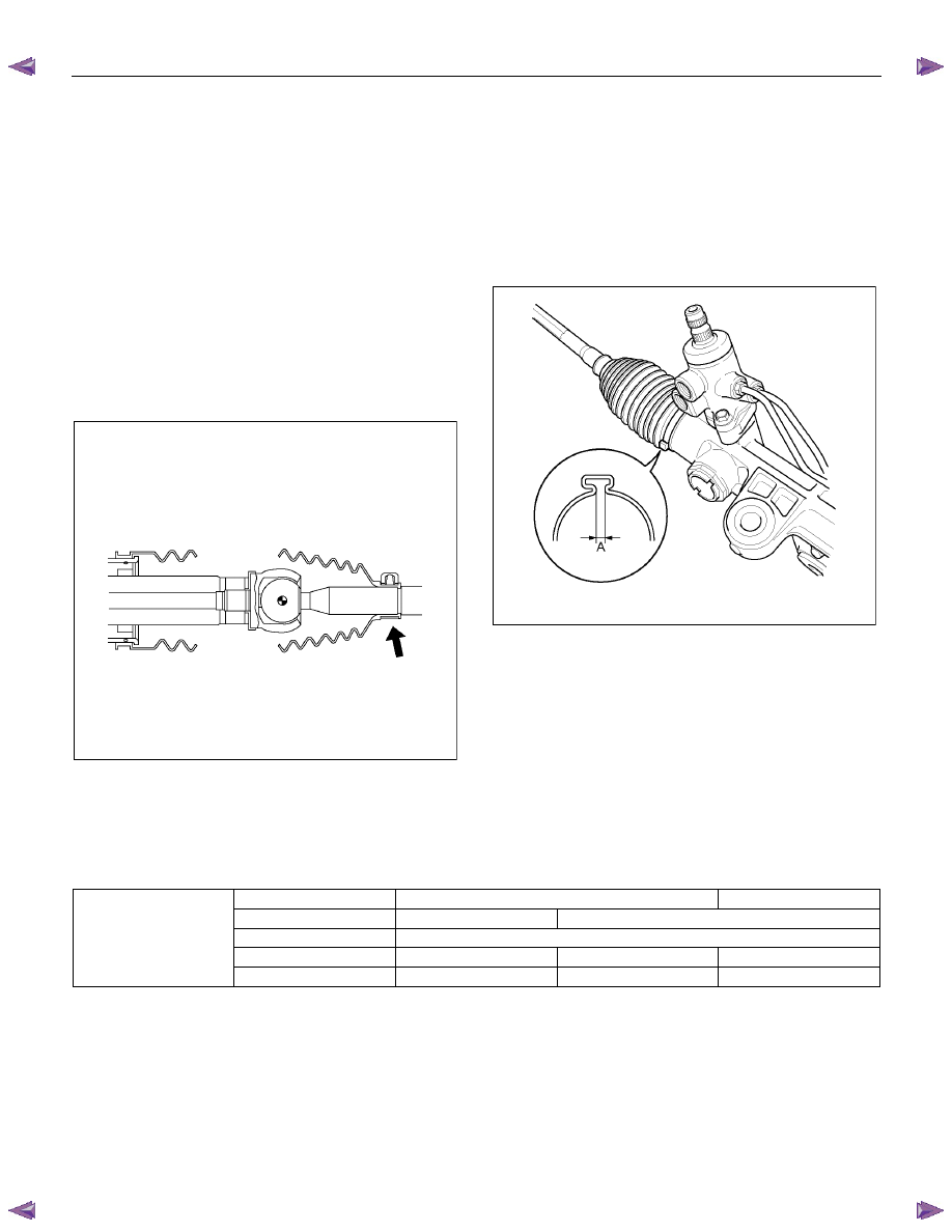
4. Apply grease to the tie-rod groove. Install bellows on
housing assembly.
CAUTION :
Make sure that there are no bulges or dents in the
bellows.
After installation, confirm the small end of the
bellows is inserted into the tie-rod groove.
RUW53BSH000301
5. Caulk the band using clamp pliers 5-8840-2745-0.
For 4
×2 except High ride suspension models;
Caulk gap(A): less than 2.0mm(0.08in).
For 4
×4 and 4×2 High ride suspension models;
Caulk gap(A): 2.6 – 3.3mm(0.10 – 0.13in).
CAUTION :
Be sure to use a new band.
RUW53BSH000601
6. Install
clip.
7. Install tie-rod end and tighten lock nut.
Torque:
98 N
⋅⋅⋅⋅m (10 kgf⋅⋅⋅⋅m/72 lb⋅⋅⋅⋅ft)
Main Data and Specifications
General Specifications
2WD
4WD
Power steering
Without
With
Type
Rack and pinion
Rack stroke mm (in)
138 (5.43)
138 (5.43)
152 (5.98)
Steering unit
Lock to lock
4.84
3.38
3.23
3B-16 POWER-ASSISTED STEERING SYSTEM
Torque Specifications
N
⋅m (kgf⋅m/Ib⋅ft)
RTW73BLF000801
Special Tools
ILLUSTRATION
TOOL NO.
TOOL NAME
ILLUSTRATION
TOOL NO.
TOOL NAME
5-8840-2005-0
(J-29107)
Tie rod end remover
5-8840-2745-0
Clamp plier

POWER-ASSISTED STEERING SYSTEM 3B-17
Power Steering Pump (4JH1-TC, 4JA1-T)
Power Steering Pump and Associated Parts
RTW53BMF000401
Legend
(1) Pump Assembly
(2) Suction Hose
(3) Flexible Hose
(4) Bolt
(5) Bracket
Removal
1. Remove the drive belt.
2. Remove the pulley
3. Place a drain pan below the pump.
4. Disconnect the suction hose.
5. Disconnect the flexible hose.
6. Remove the power steering fixing bolt and remove
the pump assembly.
Installation
1. Install the pump assembly to the pump braket,
tighten the fixing bolt to the specified torque.
Torque: 40 N·m (4.1 kgf·m/30 lb·ft)
2. Install the flexible hose.
Tighten the nut to specified torque.
Torque: 20 N·m (2.0 kgf·m/14 lb·ft)
3. Install the pulley and tighten the bolt to the specified
torque.
Torque: 28 N·m (2.9 kgf·m/21 lb·ft)
4. Install the drive belt.
5. Connect the suction hose, then fill and bleed system.
Refer to Bleeding the Power Steering System in this
section.
3B-18 POWER-ASSISTED STEERING SYSTEM
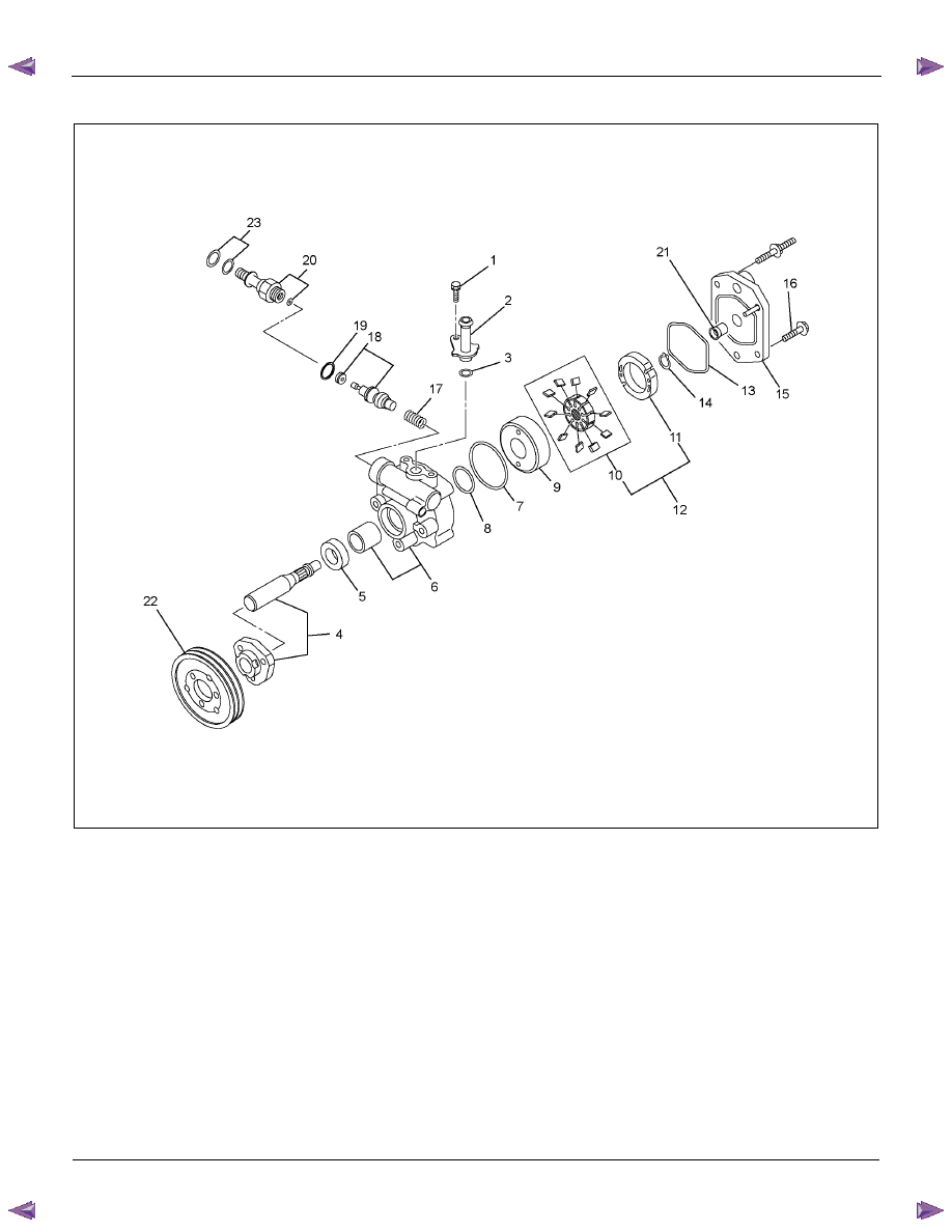
Power Steering Pump Disassembled View
RTW63BLF000301
Legend
(1) Bolt
(2) Suction Pipe
(3) O-ring
(4) Shaft Assembly
(5) Oil Seal
(6) Front Housing
(7) O-ring
(8) O-ring
(9) Side Plate
(10) Rotor and Vane
(11) Cam
(12) Pump Cartridge Assembly
(13) O-ring
(14) Snap
Ring
(15) Rear
Housing
(16) Bolt
(17) Spring
(18) Relief
Valve
(19) O-ring
(20) Connector
(21) Bush
(22) Pulley
(23) O-ring
Нет комментариевНе стесняйтесь поделиться с нами вашим ценным мнением.
Текст