Isuzu KB P190. Manual — part 68
POWER-ASSISTED STEERING SYSTEM 3B-11
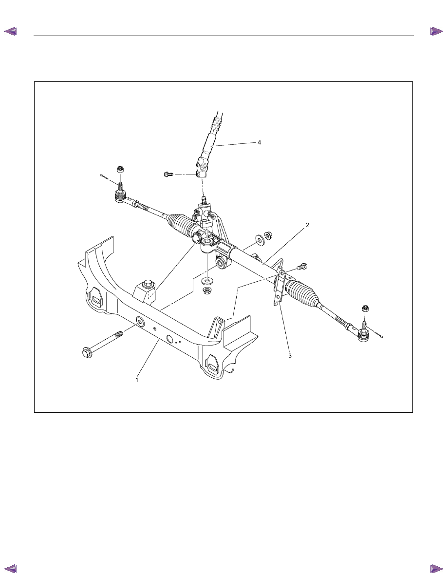
Power Steering Unit
Power Steering Unit and Associated Parts
431R300016
Legend
(1) Crossmember
(2) Power Steering Unit Assembly
(3) Bracket
(4) Universal joint (Steering shaft)
Removal
1. Remove the universal joint assembly.
Make a setting mark across the coupling flange and
steering unit to insure reassembly of the parts in the
original position.
2. Drain power steering fluid.
3. Remove the tie rod end assembly from knuckle.
Use tie rod end remover 5-8840-2005-0.
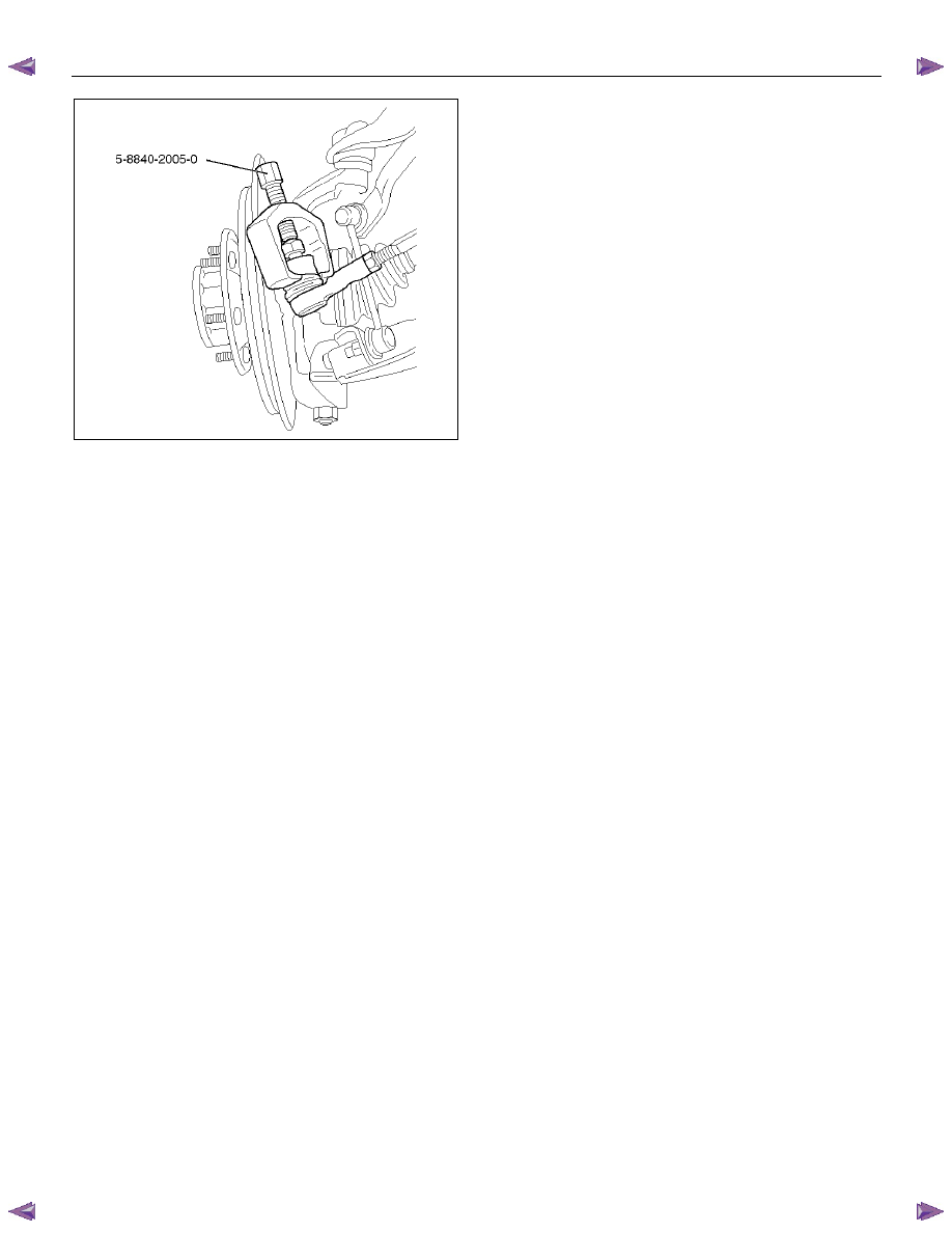
3B-12 POWER-ASSISTED STEERING SYSTEM
901RW270
4. Disconnect the feed line and return line from
steering unit.
Remove the clips on the crossmember and frame.
Wire the power steering line to frame.
NOTE: Take care to prevent foreign matter from
entering when disconnecting the power steering line.
5. Remove the power steering unit from the
crossmember.
Installation
1. Install power steering unit on crossmember.
Tighten fixing bolt and nut to specified torque.
Torque:
116 N
⋅⋅⋅⋅m (11.8 kgf⋅⋅⋅⋅m/85 lb⋅⋅⋅⋅ft)
Torque:
220 N
⋅⋅⋅⋅m (22.4 kgf⋅⋅⋅⋅m/162 lb⋅⋅⋅⋅ft)
2. Connect the feed line and return line.
Torque:
25 N
⋅⋅⋅⋅m (2.5 kgf⋅⋅⋅⋅m/18 lb⋅⋅⋅⋅ft)
3. Install tie-rod end assembly on knuckle.
Torque:
98 N
⋅⋅⋅⋅m (10 kgf⋅⋅⋅⋅m/72 lb⋅⋅⋅⋅ft)
4. Align the setting marks on the universal joint
(applied at disassembly) with the setting marks on
the power steering unit. Connect the universal joint
assembly to the power steering unit.
5. Tighten the universal joint bolt to the specified
torque.
Torque:
31 N
⋅⋅⋅⋅m (3.2 kgf⋅⋅⋅⋅m/23 lb⋅⋅⋅⋅ft)
6. Install the stone guard.
7. Bleed the system.
Refer to Bleeding the Power Steering System in this
section.
POWER-ASSISTED STEERING SYSTEM 3B-13
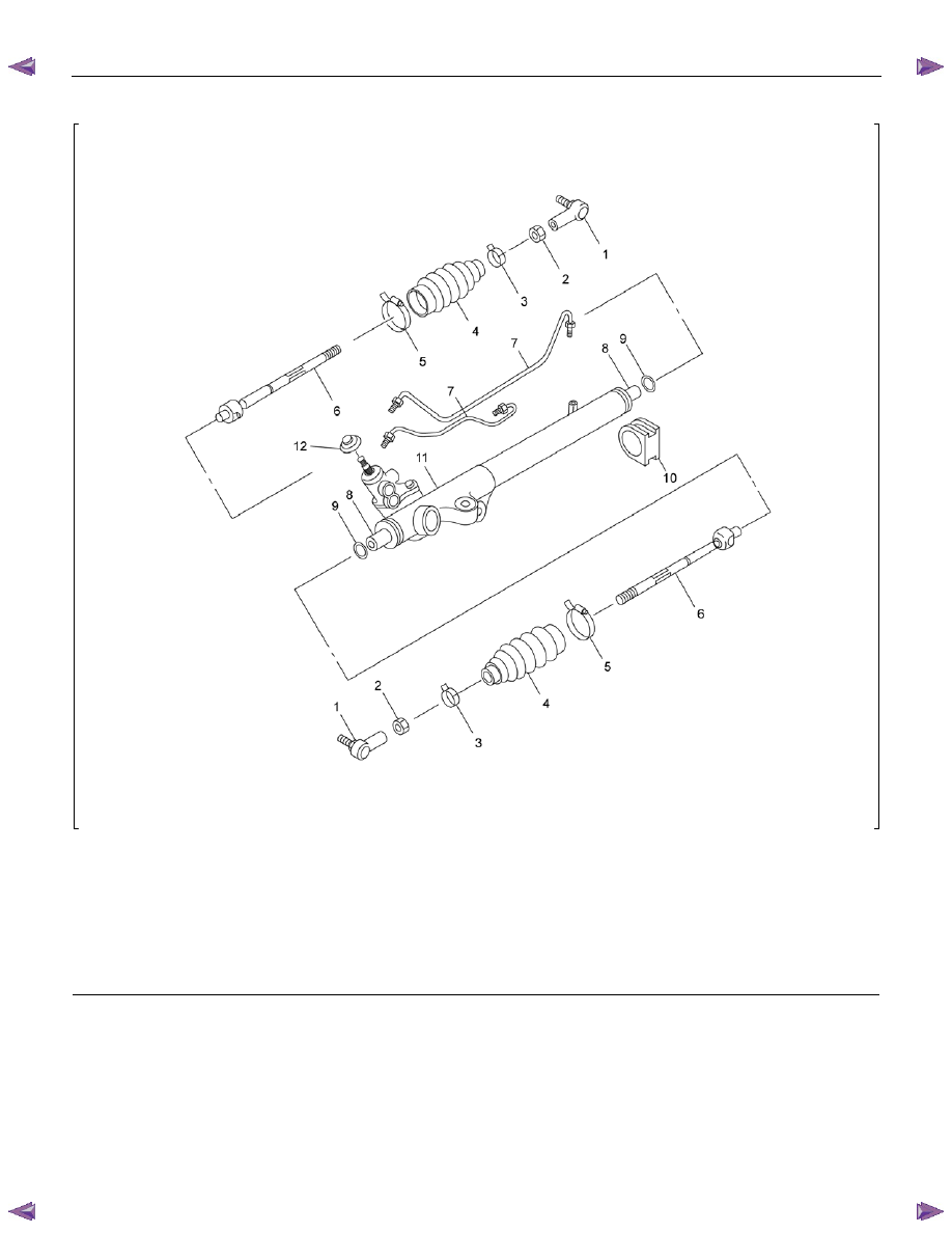
Power Steering Unit Disassembled View
RTW53BLF000401
Legend
(1) Tie-rod End
(2) Lock Nut
(3) Clip
(4) Bellows
(5) Band
(6) Tie-rod Assembly
(7) Oil Line
(8) Rack Bar
(9) Tab Washer
(10) Mounting Rubber
(11) Housing Assembly
(12) Dust Cover
3B-14 POWER-ASSISTED STEERING SYSTEM
Disassembly
NOTE : The valve hosing is made of aluminum and care
should be exercised when clamping in a vise, etc.
to prevent distortion or damage.
For the left side, follow the same steps as right side.
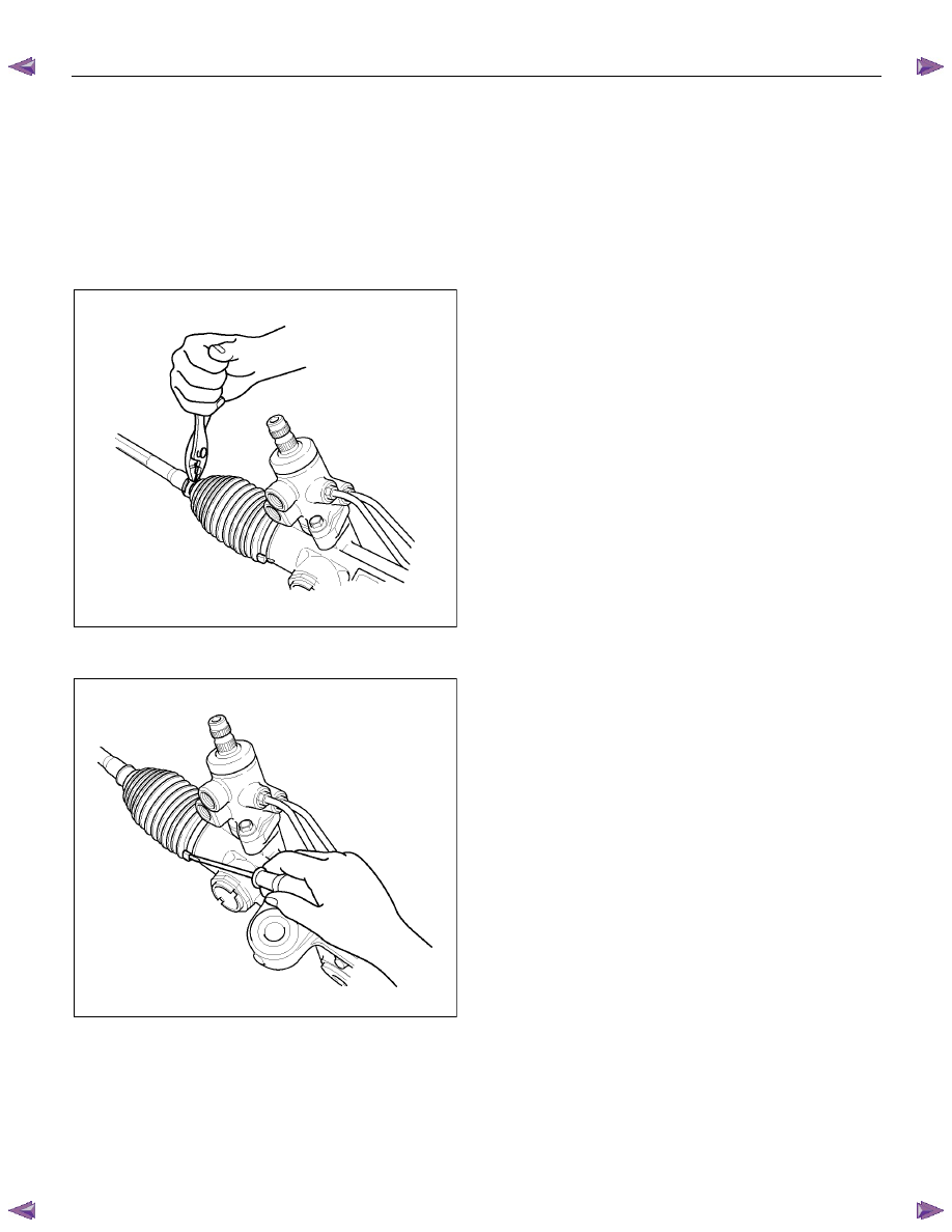
1. Loosen lock nut and remove tie-rod end.
2. Remove clip and band, then remove bellows.
• Use a pair of pliers to open the clip. Slide the clip
toward the tie-rod end.
RUW53BSH000401
• Remove band from the bellows by using
screwdriver.
RUW53BSH000501
CAUTION :
For 4
××××2 except High ride suspension models;
The band is not reusable. If removed, it must be
replaced with a new one.
Take care not to damage the bellows during band
removal.
For 4
××××4 and 4××××2 High ride suspension models;
The band and bellows are not reusable. If removed,
they must be replaced with a new one.
3. Remove tie-rod assembly.
To remove, move the boot toward the tie-rod end,
then remove tab washer.
4. Remove oil line, mounting rubber and dust cover.
Inspection and Repair
Make necessary correction or parts replacement if wear,
damage, corrosion or any other abnormal condition are
found during inspection.
Check the following parts.
1. Tie-rod
end
2. Lock
nut
3. Clip
4. Bellows
5. Band
Tie-Rod End
If looseness or play is found when checked by moving
the end of ball joint at tie-rod end, replace tie-rod end.
Tie-Rod Assembly
If the resistance is insufficient or play is felt when
checked by moving the ball on the tie-rod, replace the
tie-rod assembly.
Rubber Parts
For 4
×2 except High ride suspension models;
If wear or damage is found during inspection, replace
with new ones.
For 4
×4 and 4×2 High ride suspension models;
Even if wear or damage is not found after removal,
replace with new ones.
Reassembly
1. Install mounting rubber and dust cover (If removed).
2. Install oil line.
Torque: 12 N
⋅⋅⋅⋅m (1.2 kgf⋅⋅⋅⋅m/104 lb⋅⋅⋅⋅in)
Нет комментариевНе стесняйтесь поделиться с нами вашим ценным мнением.
Текст