Isuzu KB P190. Manual — part 671
Engine Mechanical – V6
Page 6A1–205
Reinstall
N O T E
The bolt holes are unevenly spaced to enable
flexplate fitment in the one position only.
1
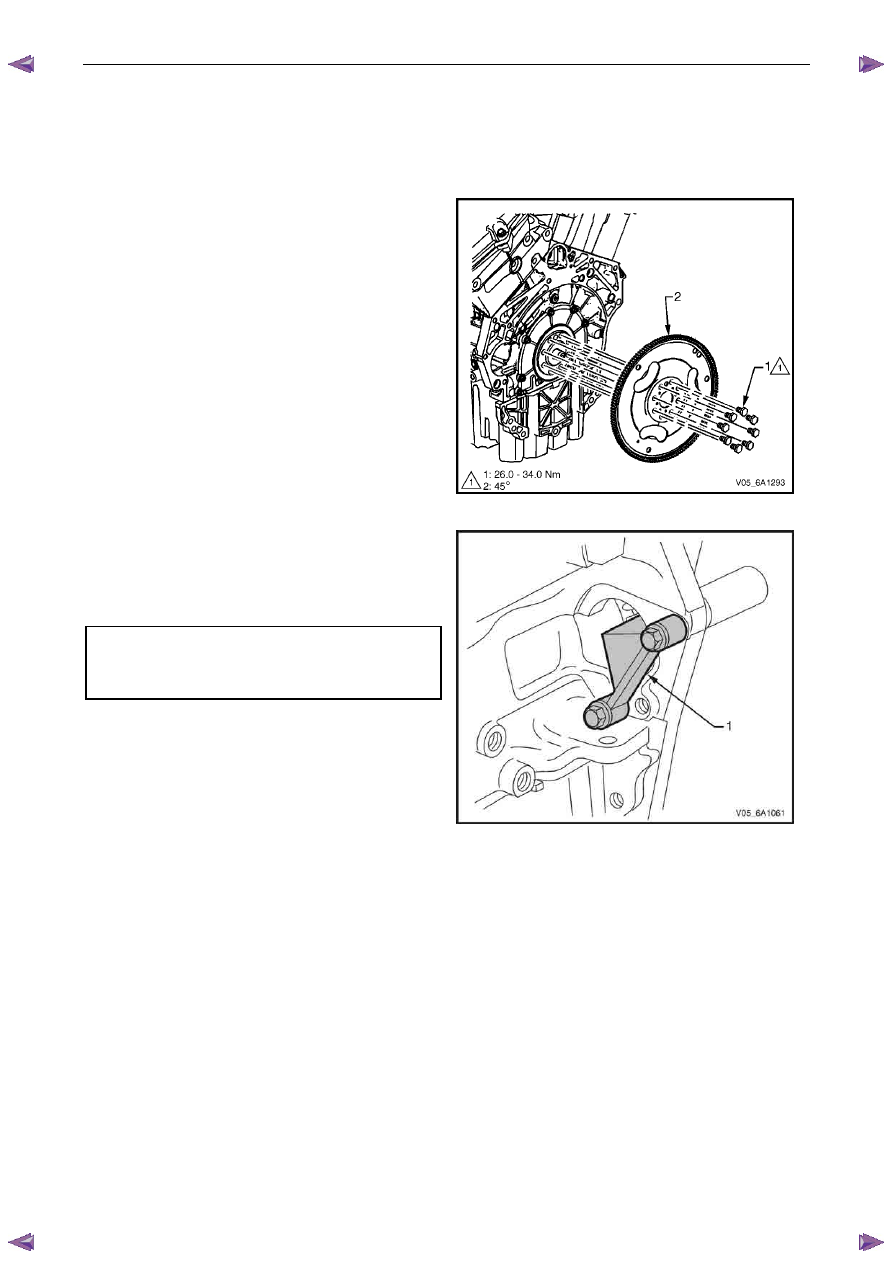
Place the flexplate assembly (2) in position on the
crankshaft.
2
Install new flexplate attaching bolts (1) and hand
tighten.
Figure 6A1 – 365
3
Install the flexplate holding tool, Tool No. EN-46106
(1) into the starter motor mounting location.
4
Tighten the eight flexplate attaching bolts to the
correct torque specification.
Flexplate attaching bolt
torque specification:
Stage 1 . . . ..26.0 – 34.0 Nm
Stage
2 . . . . . . . . .45°
5
Remove the flexplate holding tool.
6
Install the starter motor, refer to 6D1-2 Starting
System – V6.
7
Install the transmission, refer to 7E4 Automatic
Transmission – 4L60E – On-vehicle Servicing.
Figure 6A1 – 366
4.4
Crankshaft Rear Seal and Plate
Assembly
Remove
1
Remove the engine assembly, refer to 4.1
Engine .
2
Remove the flexplate assembly, refer to 4.3
Flexplate Assembly.
3
Remove the engine oil pan assembly, refer to 4.2
Oil Pan and Oil Pump Suction Pipe Assembly.
Engine Mechanical – V6
Page 6A1–206
4
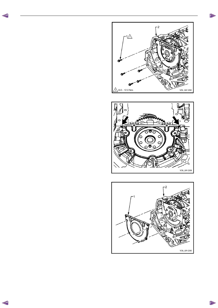
Remove the five bolts (1) attaching the crankshaft
rear seal housing to the rear of the cylinder block (2).
Figure 6A1 – 367
5
Shear the RTV sealant using the prise points located
at the edge of the crankshaft rear oil seal housing,
Figure 6A1 – 368
6
Remove the crankshaft rear oil seal housing (1) from
the cylinder block (2).
Figure 6A1 – 369
Engine Mechanical – V6
Page 6A1–207
Reinstall
1
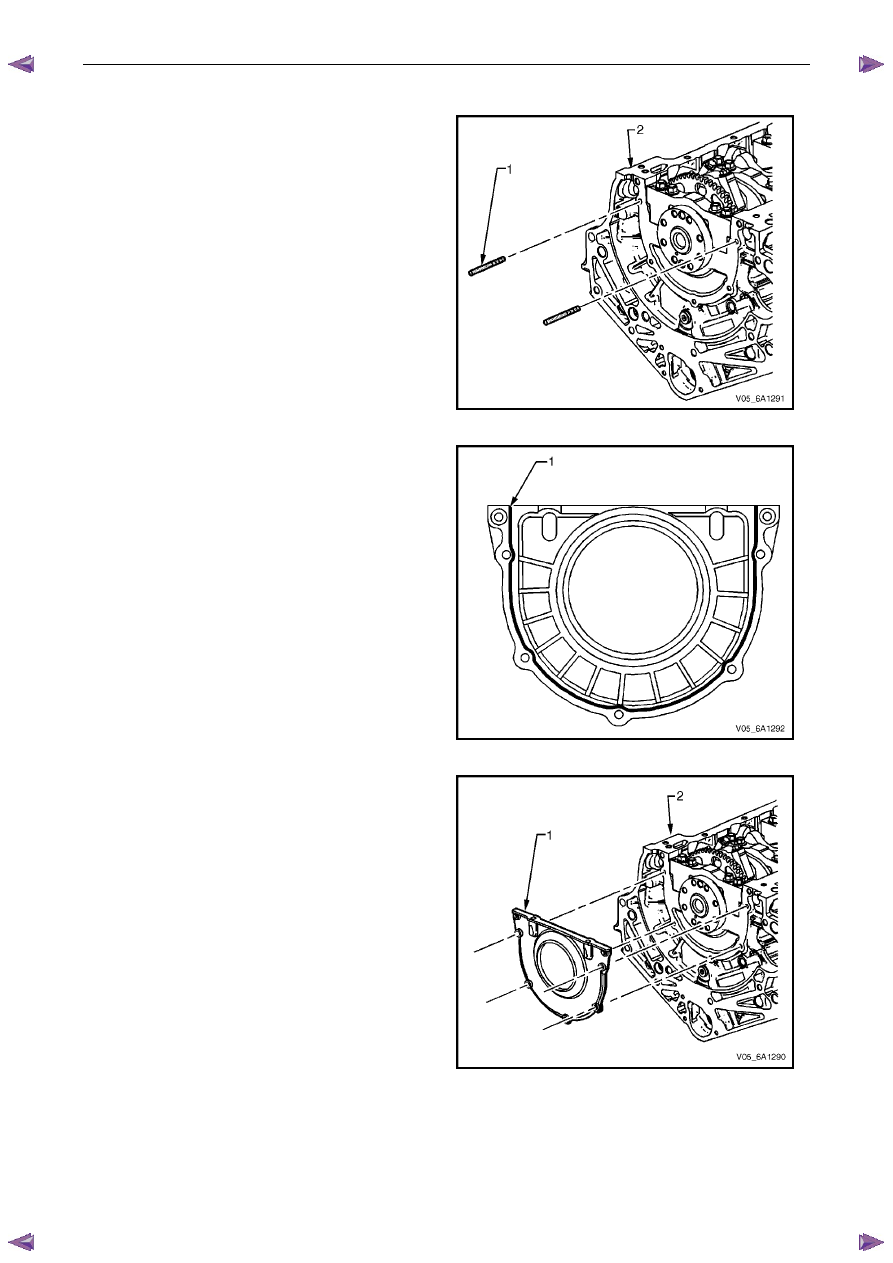
Install the guide pins, Tool No. EN-46109 (1) into the
two crankshaft rear oil seal housing bolt holes of the
cylinder block (2).
Figure 6A1 – 370
2
Apply a 3mm bead (1) of RTV sealant to the
crankshaft rear oil seal housing.
Figure 6A1 – 371
3
Install the crankshaft rear oil seal housing (1) to the
cylinder block (2).
N O T E
• Do not allow any engine oil onto the cylinder
block mating surface, where the crankshaft
rear oil seal housing is to be installed.
• A seal-protector is provided with the new
crankshaft rear seal and housing assembly.
Do not remove the seal protector from the
crankshaft rear oil seal housing until the
crankshaft rear oil seal housing is fully in
position.
4
Remove the guide pins from the cylinder block.
Figure 6A1 – 372
Engine Mechanical – V6
Page 6A1–208
5
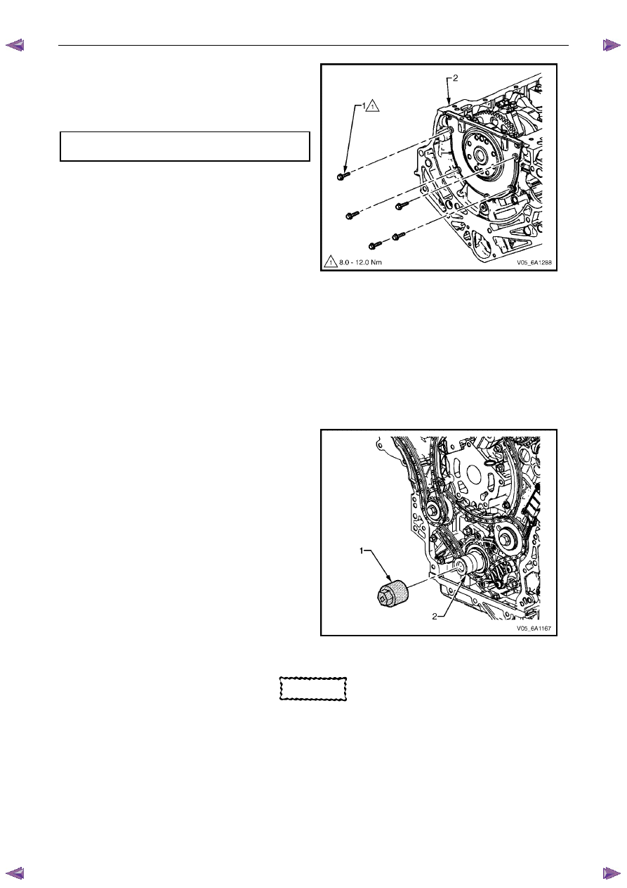
Install the crankshaft rear oil seal housing attaching
bolts (1) to the cylinder block (2) and tighten to the
correct torque specification.
Crankshaft rear oil seal housing
attaching bolt torque specification. . . .8.0 – 12.0 Nm
Figure 6A1 – 373
4.5
Pistons, Pins, Rings, Connecting Rods
and Big-end Bearings
Remove
1
Remove the engine assembly, refer to 4.1
Engine .
2
Remove both cylinder head assemblies, refer to 3.22
Cylinder Head Assembly.
3
Remove the oil pan assembly, refer to 4.2
Oil Pan and Oil Pump Suction Pipe Assembly.
4
Mark the top of the piston being removed to identify its specific bore.
5
Install Tool No. EN-46111 (1) onto the crankshaft (2).
6
Rotate the crankshaft until the piston being removed
is at the bottom of its stroke; bottom dead centre
(BDC).
Figure 6A1 – 374
CAUTION
If the connecting rod bearings have been
used in a running engine, they must be
replaced with new connecting rod bearings
for reassembly.
7
Before removing the connecting rods, check the connecting rod side clearance using the following procedure:
a
Tap the connecting rod to one end of the crankshaft journal with a dead blow or wooden hammer.
b
Using feeler gauges, measure the clearance between the crankshaft counterweight and the connecting rod.
c
The connecting rod side clearance should not exceed specifications, refer to 5 Specifications.
Нет комментариевНе стесняйтесь поделиться с нами вашим ценным мнением.
Текст