Isuzu KB P190. Manual — part 672
Engine Mechanical – V6
Page 6A1–209
d
If the endplay exceeds the specified limits, measure the width of the crankpin end of the connecting rod, refer
to 5
Specifications.
e
If the connecting rod width is significantly smaller than specified and severe wear is present on the side of the
connecting rod, replace the connecting rod.
f
If the connecting rod width is within specification and excessive scoring is present on the crankshaft journals,
replace the crankshaft.
CAUTION
Do not use a stamp, punch or any other
method that may distort or stress the
connecting rod and cap. Extensive engine
damage may result from a connecting rod that
is distorted or stressed.
8
Mark the cylinder number on the connecting rod and the connecting rod cap with a paint stick or permanent marker.
CAUTION
Powdered metal connecting rods have rod
bolts which yield when tighten to the
specified torque. If the bolts are loosened or
removed they must be replaced. Rod bolts
that are not replaced will not torque to the
correct clamp load and can lead to serious
engine damage.
9
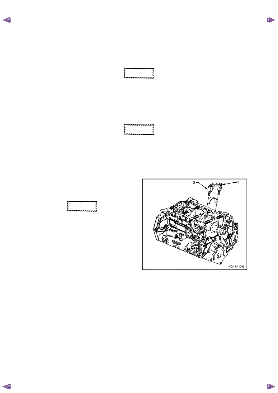
Remove the connecting rod bolts (1), loosening
progressively from side to side.
CAUTION
The connecting rod caps must remain with
the original connecting rod.
10
Remove the connecting rod cap (2).
Figure 6A1 – 375
Engine Mechanical – V6
Page 6A1–210
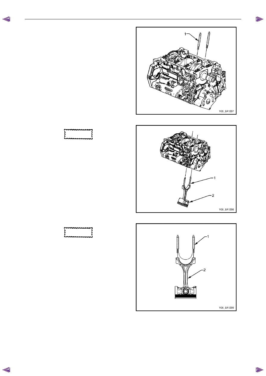
11
Install connecting rod guide pin set, Tool No.
EN-46121 (1) to the connecting rod bolt holes.
Figure 6A1 – 376
CAUTION
Do not damage the crankshaft journal,
cylinder wall and piston cooling jets when
removing the connecting rod and piston
assembly.
12
Using connecting rod guide pin set, Tool No.
EN-46121 (1), push the connecting rod and piston
assembly (2) through the top of the cylinder.
Figure 6A1 – 377
CAUTION
When dismantled, ensure the connecting
rod, connecting rod cap, piston and
bearings are organised in their original
position and location. This will also aid
engine mechanical diagnosis.
13
Remove connecting rod guide pin set, Tool No.
EN-46121 (1) from the connecting rod bolt holes.
14
Remove the upper connecting rod bearing from the
connecting rod (2).
Figure 6A1 – 378
Engine Mechanical – V6
Page 6A1–211
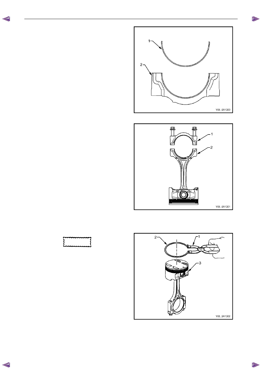
15
Remove the lower connecting rod bearing (1) from
the connecting rod cap (2).
Figure 6A1 – 379
N O T E
The cap and rod are a matched set and must be
kept together.
16
Reattach the connecting rod cap (1) to the connecting
rod (2) to prevent damage to their mating surfaces.
17
Repeat steps 4 to 16 for the remaining piston and
connecting rod assemblies.
Figure 6A1 – 380
Disassemble
CAUTION
A piston ring expander must be used to
remove and install the piston rings. Only
expand the rings far enough to fit over the
piston lands. If the rings are overexpanded,
the top ring will shatter and the others will
distort.
1
Remove the piston rings (2) using a piston ring
expander (1). Place each ring in a clean shop towel
for storage.
Figure 6A1 – 381
Engine Mechanical – V6
Page 6A1–212
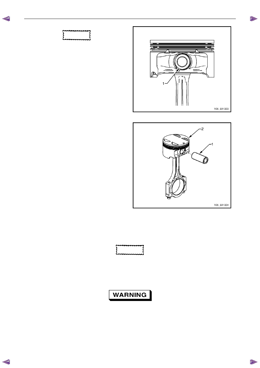
CAUTION
Do not reuse the piston pin retainers.
2
Remove the piston pin retainers by using the removal
access notch (1) in the side of the piston. Discard the
piston pin retainers.
Figure 6A1 – 382
3
Slide the piston pin (1) out of the piston (2). The
piston will disconnect from the connecting rod.
Figure 6A1 – 383
Clean and Inspect
Piston Cleaning Procedure
CAUTION
Do not use a wire brush to clean any part of
the piston.
1
Clean the piston skirts and the pins with a suitable solvent.
2
Clean the piston ring grooves with a groove cleaner. Ensure the oil ring holes and slots are clean.
Safety glasses must be worn when using
compressed air.
3
Dry the piston with compressed air.
Нет комментариевНе стесняйтесь поделиться с нами вашим ценным мнением.
Текст