Isuzu KB P190. Manual — part 575

6E–130
ENGINE DRIVEABILITY AND EMISSIONS
8
Substitute a known good IAT sensor assembly and
recheck.
Was the problem solved?
—
Go to Step 9
Go to Step 10
9
Replace the IAT sensor assembly.
Is the action complete?
—
Verify repair
—
10
Is the ECM programmed with the latest software
release?
If not, download the latest software to the ECM using
the “SPS (Service Programming System)”.
Was the problem solved?
—
Verify repair
Go to Step 11
11
Replace the ECM.
Is the action complete?
IMPORTANT: The replacement ECM must be
programmed. Refer to section of the Service
Programming System (SPS) in this manual.
Following ECM programming, the immobilizer system
(if equipped) must be linked to the ECM. Refer to
section 11 “Immobilizer System-ECM replacement” for
the ECM/Immobilizer linking procedure.
—
Verify repair
—
Step
Action
Value(s)
Yes
No
ENGINE DRIVEABILITY AND EMISSIONS
6E–131
DIAGNOSTIC TROUBLE CODE (DTC) P0113 INTAKE AIR TEMPERATURE
SENSOR HIGH INPUT
Condition for setting the DTC and action taken when the DTC sets
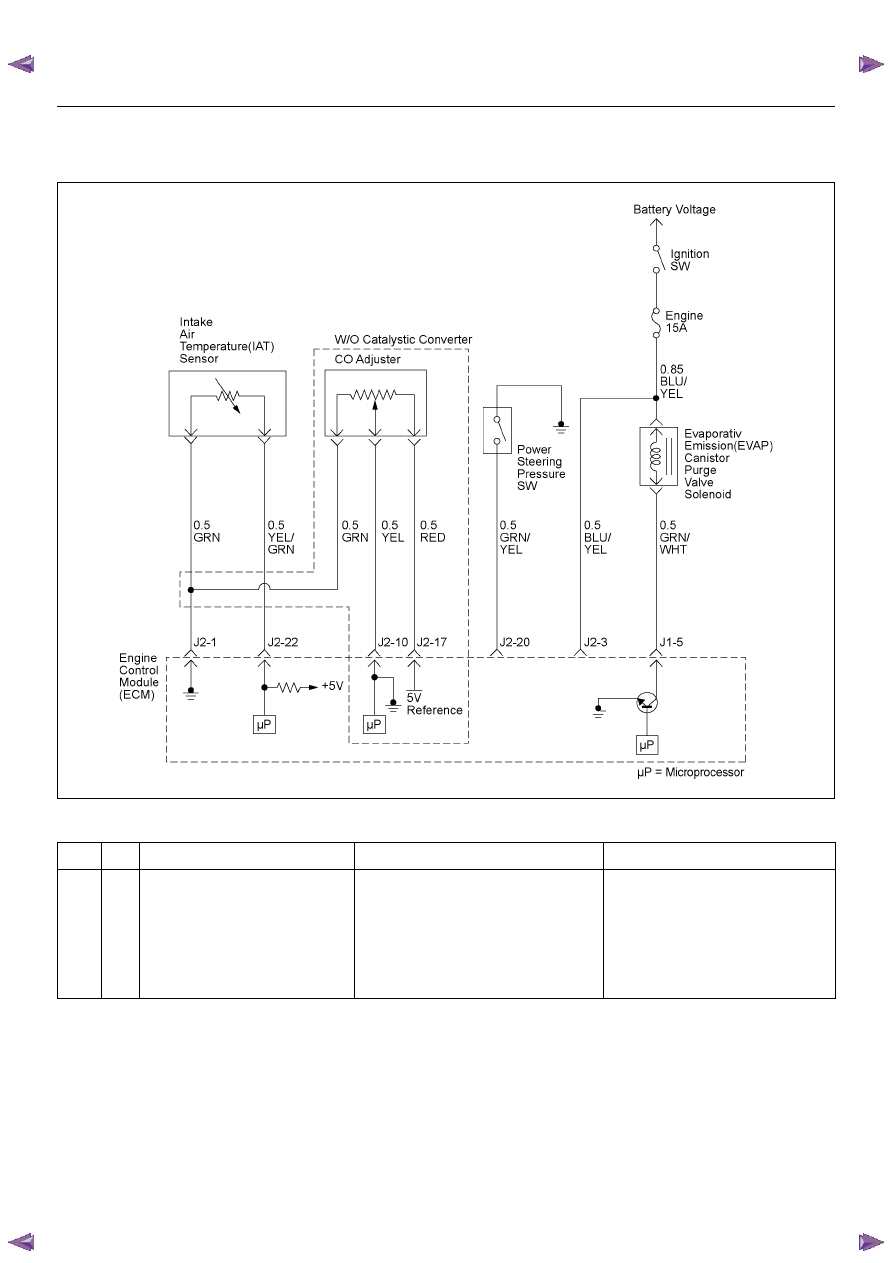
Circuit Description
The intake air temperature (IAT) sensor is a thermistor
which measures the temperature of the air entering the
engine. The engine control module (ECM) applies 5
volts through a pull-up resistor to the IAT sensor. When
the intake air is cold, the sensor resistance is high and
the ECM will monitor a high signal voltage on the IAT
signal circuit. If the intake air is warm, the sensor
resistance is lower causing the ECM to monitor a lower
voltage. Diagnostic Trouble Code P0113 will set when
the ECM detects an excessively high signal voltage on
the intake air temperature sensor signal circuit.
Diagnostic Aids
Check for the following conditions:
• Poor connection at ECM - Inspect harness
connectors for backed-out terminals, improper
mating, broken locks, improperly formed or damaged
Code
Type
DTC Name
DTC Setting Condition
Fail-Safe (Back Up)
P0113
A
Intake Air Temperature Sensor High
Input
1. No DTC relating to VSS & ECT sensor.
2. Vehicle speed is below 70km/h.
3. 3Engine coolant temperature is more than -
8 deg. C.
4. Engine run time is longer than 120 sec-
onds.
5. Mass air flow is below 30g/s.
6. IAT sensor output is below -38 deg. C.
The ECM uses 20 deg. C condition as
substitute.
6E–132
ENGINE DRIVEABILITY AND EMISSIONS
terminals, and poor terminal-to-wire connection.
• Damaged harness - Inspect the wiring harness for
damage, short to ground, short to battery positive,
and open circuit. If the harness appears to be OK,
observe the IAT display on the Tech 2 while moving
connectors and wiring harnesses related to the IAT
sensor. A change in the IAT display will indicate the
location of the fault.
Diagnostic Trouble Code (DTC) P0113
Intake Air Temperature Sensor High Input
Step
Action
Value(s)
Yes
No
1
Was the “On-Board Diagnostic (OBD) System Check”
performed?
—
Go to Step 2
Go to On Board
Diagnostic
(OBD) System
Check
2
1. Connect the Tech 2.
2. Review and record the failure information.
3. Select “F0: Read DTC Infor By Priority” in “F0:
Diagnostic Trouble Code”.
Is the DTC P0113 stored as “Present Failure”?
—
Go to Step 3
Refer to
Diagnostic Aids
and Go to Step
3
3
1. Using the Tech2, ignition “On” and engine “Off”.
2. Select “Clear DTC Information” with the Tech2 and
clear the DTC information.
3. Operate the vehicle and monitor the “F5: Failed
This Ignition” in “F2: DTC Information”.
Was the DTC P0113 stored in this ignition cycle?
—
Go to Step 4
Refer to
Diagnostic Aids
and Go to Step
4
4
Check for poor/faulty connection at the IAT sensor or
ECM connector. If a poor/faulty connection is found,
repair as necessary.
Was the problem found?
—
Verify repair
Go to Step 5
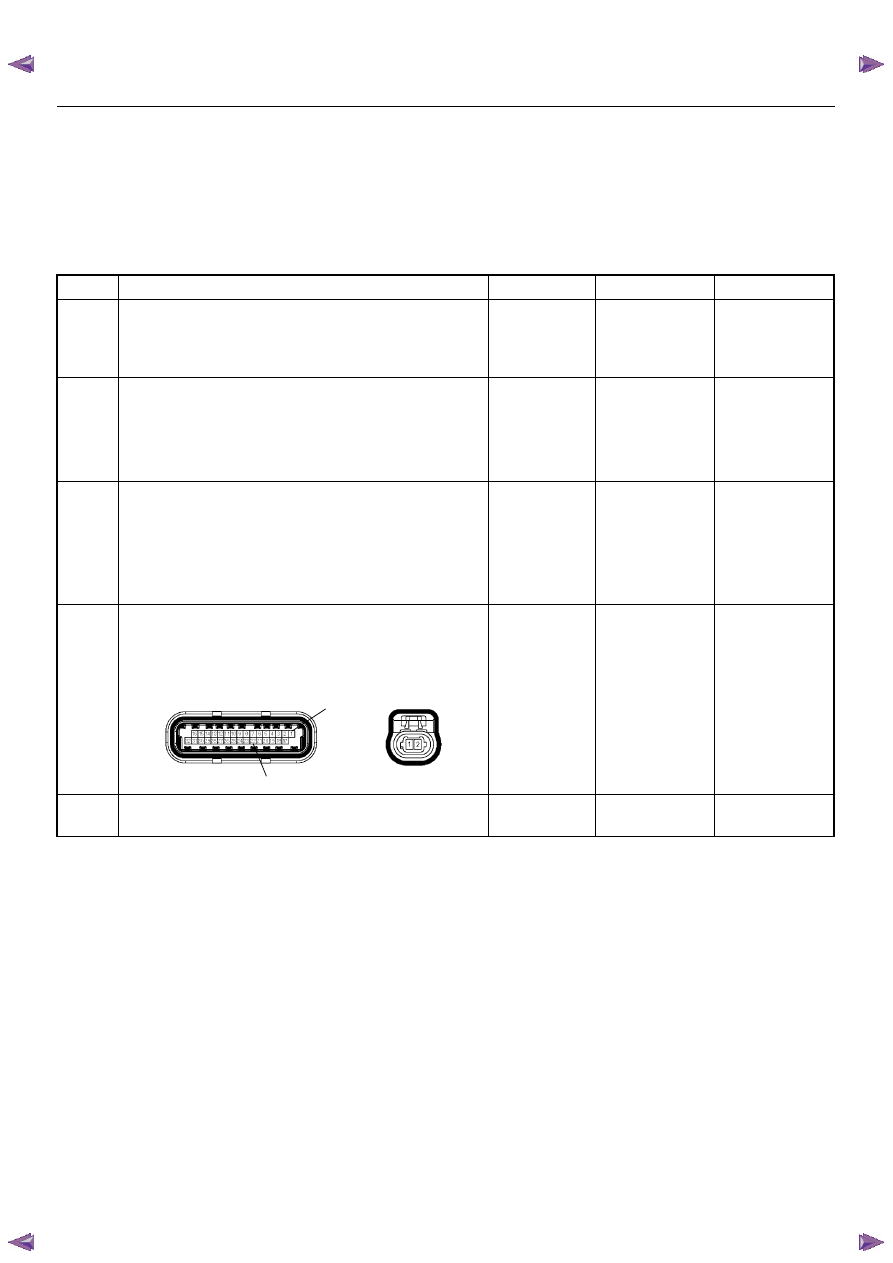
5
Visually check the IAT sensor.
Was the problem found?
—
Go to Step 12
Go to Step 6
C56(J2)
C121
1
22
ENGINE DRIVEABILITY AND EMISSIONS
6E–133
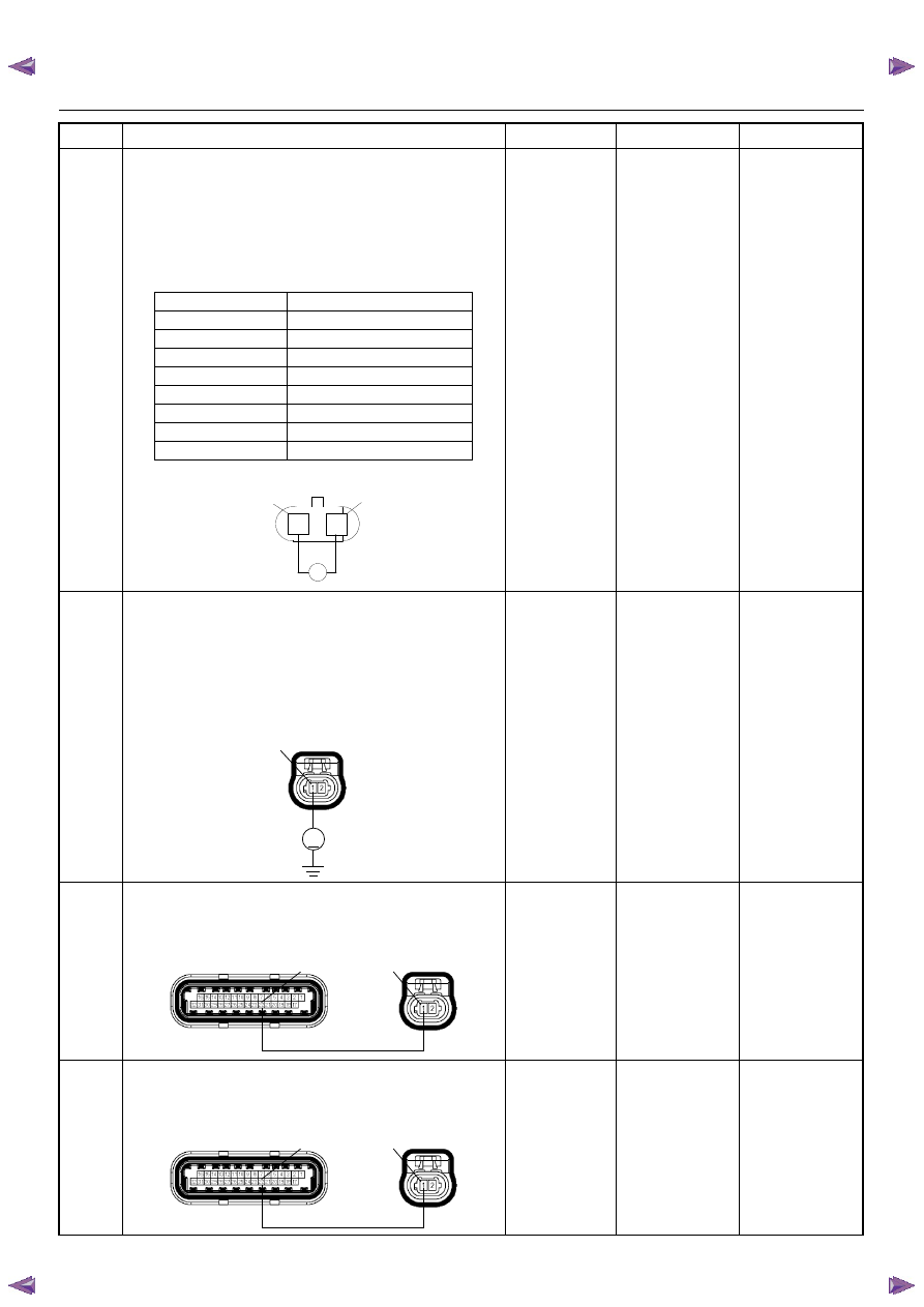
6
Using the DVM and check the IAT sensor.
1. Ignition “Off”, engine “Off”.
2. Disconnect IAT sensor connector.
3. Measure the resistance of IAT sensor.
Does the tester indicate standard resistance as shown
in the following table?
Standard
resistance
Go to Step 7
Go to Step 12
7
Using the DVM and check the IAT sensor signal
circuit.
1. Ignition “On”, engine “Off”.
2. Disconnect the IAT sensor connector.
3. Check the circuit for open circuit.
Was the DVM indicated specified value?
Approximately
5.0V
Go to Step 10
Less than 1V:
Go to Step 8
More than
specified value:
Go to Step 9
8
Repair the open circuit between the ECM and IAT
sensor.
Was the problem solved?
—
Verify repair
Go to Step 14
9
Repair the short to voltage circuit between the ECM
and IAT sensor.
Was the problem solved?
—
Verify repair
Go to Step 14
Step
Action
Value(s)
Yes
No
Temperature (°C)
Resistance (
Ω) (Approximately)
-20
32500
0
9910
20
3400
40
1509
60
670
80
329
100
182
120
101
2
1
IAT Sensor
Ω
1
2
V
C121
1
C56(J2)
C121
1
22
C56(J2)
C121
1
22
Нет комментариевНе стесняйтесь поделиться с нами вашим ценным мнением.
Текст