Isuzu KB P190. Manual — part 573

6E–122
ENGINE DRIVEABILITY AND EMISSIONS
12
Replace the ECM.
Is the action complete?
IMPORTANT: The replacement ECM must be
programmed. Refer to section of the Service
Programming System (SPS) in this manual.
Following ECM programming, the immobilizer system
(if equipped) must be linked to the ECM. Refer to
section 11 “Immobilizer System-ECM replacement” for
the ECM/Immobilizer linking procedure.
—
Verify repair
—
Step
Action
Value(s)
Yes
No

ENGINE DRIVEABILITY AND EMISSIONS
6E–123
DIAGNOSTIC TROUBLE CODE (DTC) P0108 MANIFOLD ABSOLUTE
PRESSURE CIRCUIT HIGH INPUT
Condition for setting the DTC and action taken when the DTC sets
Circuit Description
The manifold absolute pressure (MAP) sensor responds
to changes in intake manifold pressure. The MAP
sensor signal voltage to the engine control module
(ECM) varies from below 2 volts at idle (low manifold
pressure) to above 4 volts with the ignition ON, engine
not running or at wide-open throttle (high manifold
pressure).
A “speed density” method of determining engine load is
used on the 2.4L engine. This is calculated using inputs
from the MAP sensor, RPM, CKP Sensor, and the
Intake Air Temperature (IAT) sensor. The MAP sensor is
the main sensor used in this calculation, and measuring
engine load is its main function.
The ECM monitors the MAP signals for voltages outside
the normal range (10-104 kPa) of the MAP sensor. If the
ECM detects a MAP signal voltage that is excessively
high, Diagnostic Trouble Code P0108 will be set.
Code
Type
DTC Name
DTC Setting Condition
Fail-Safe (Back Up)
P0108
A
Manifold Absolute Pressure Circuit
High Input
1. No DTC relating to TPS.
2. Throttle position is below 15% if engine
speed is below 2500rpm, or throttle posi-
tion is below 35% if engine speed is more
than 2500rpm.
3. Engine run time is longer than 10 seconds.
4. MAP sensor output is more than 103kPa.
The ECM uses default manifold absolute
pressure value based on engine speed
and throttle position.
6E–124
ENGINE DRIVEABILITY AND EMISSIONS
Diagnostic Aids
Check for the following conditions:
• Poor connection at ECM - Inspect harness
connectors for backed-out terminals, improper
mating, broken locks, improperly formed or damaged
terminals, and poor terminal-to-wire connection.
• If these codes are also set, it could indicate a
problem with the 5 Volt reference circuit.
• Damaged harness - Inspect the wiring harness for
damage; an open circuit, a short to ground, or a short
to voltage. If the harness appears to be OK, observe
the MAP display on the Tech 2 while moving
connectors and wiring harnesses related to the
sensor. A change in the display will indicate the
location of the fault.
Diagnostic Trouble Code (DTC) P0108
Manifold Absolute Pressure Circuit High Input
Step
Action
Value(s)
Yes
No
1
Was the “On-Board Diagnostic (OBD) System Check”
performed?
—
Go to Step 2
Go to On Board
Diagnostic
(OBD) System
Check
2
1. Connect the Tech 2.
2. Review and record the failure information.
3. Select “F0: Read DTC Infor By Priority” in “F0:
Diagnostic Trouble Code”.
Is the DTC P0108 stored as “Present Failure”?
—
Go to Step 3
Refer to
Diagnostic Aids
and Go to Step
3
3
1. Using the Tech2, ignition “On” and engine “Off”.
2. Select “Clear DTC Information” with the Tech2 and
clear the DTC information.
3. Operate the vehicle and monitor the “F5: Failed
This Ignition” in “F2: DTC Information”.
Was the DTC P0108 stored in this ignition cycle?
—
Go to Step 4
Refer to
Diagnostic Aids
and Go to Step
4
4
Check for poor/faulty connection at the MAP sensor or
ECM connector. If a poor/faulty connection is found,
repair as necessary.
Was the problem found?
—
Verify repair
Go to Step 5
5
Visually check the MAP sensor.
Was the problem found?
—
Go to Step 11
Go to Step 6
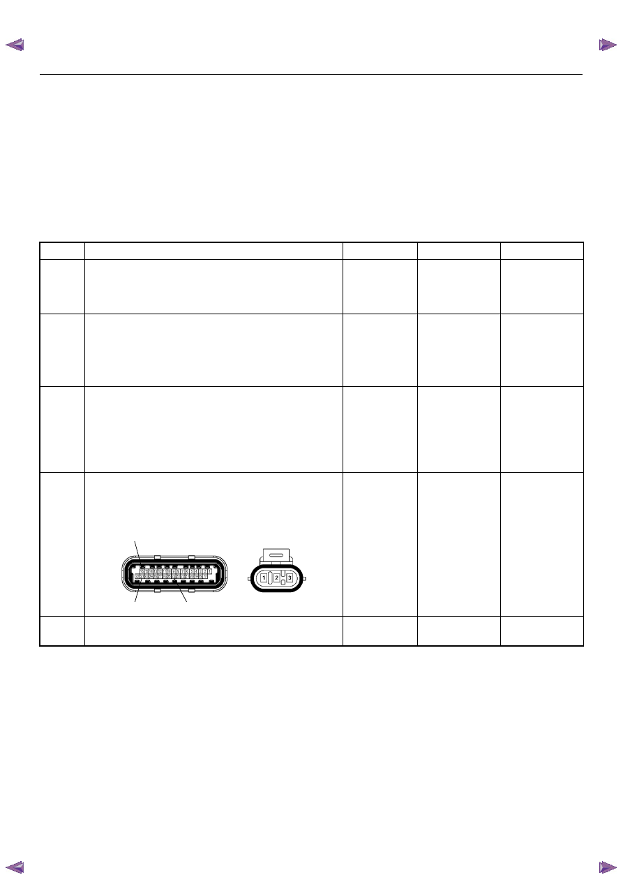
16
31
24
E85
E60(J1)

ENGINE DRIVEABILITY AND EMISSIONS
6E–125
6
Using the DVM and check the MAP sensor power
supply circuit.
1. Ignition “On”, engine “Off”.
2. Disconnect the MAP sensor connector.
3. Check the circuit for short to voltage circuit.
Was the DVM indicated specified value?
Approximately
5.0V
Go to Step 8
Go to Step 7
7
Repair the short to voltage circuit between the ECM
and MAP sensor.
Was the problem solved?
—
Verify repair
Go to Step 13
8
Using the DVM and check the MAP sensor signal
circuit.
1. Ignition “On”, engine “Off”.
2. Disconnect the MAP sensor connector.
3. Check the circuit for short to power supply circuit.
Was the DVM indicated specified value?
Less than 1V
Go to Step 9
Repair faulty
harness and
verify repair
9
Using the DVM and check the MAP sensor ground
circuit.
1. Ignition “On”, engine “Off”.
2. Disconnect the MAP sensor connector .
3. Check the circuit for short to power supply circuit.
Was the DVM indicated specified value?
Less than 1V
Go to Step 10
Repair faulty
harness and
verify repair
Step
Action
Value(s)
Yes
No
V
E85
3
31
3
E85
E60(J1)
V
E85
2
V
E85
1
Нет комментариевНе стесняйтесь поделиться с нами вашим ценным мнением.
Текст