Isuzu KB P190. Manual — part 1075
7A2-16 TRANSMISSION CONTROL SYSTEM (JR405E)
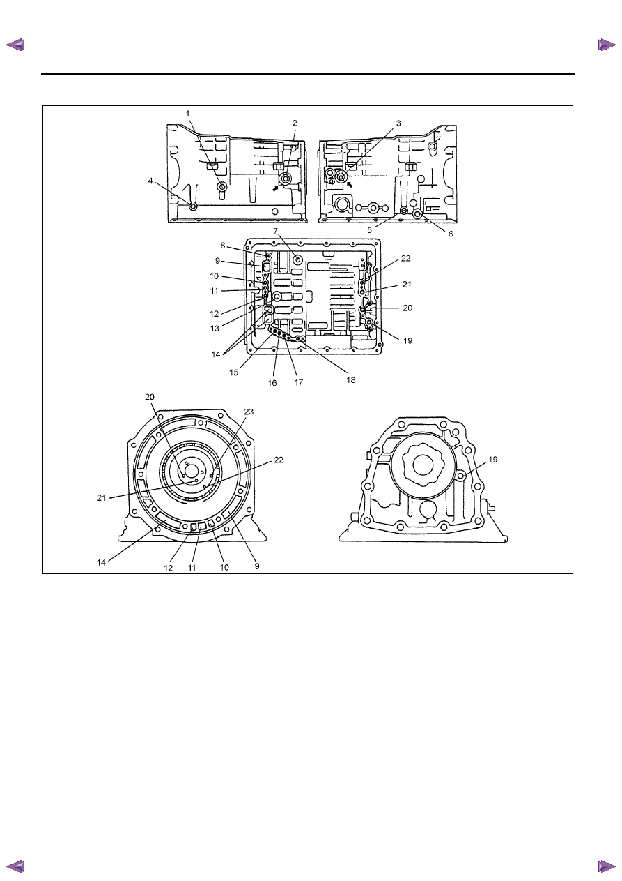
Transmission Fluid Passages (Main Unit)
Legend
1. Oil cooler (outlet)
2. Low & reverse brake pressure detection port (R range
line pressure detection port)
3. Low clutch pressure detection port (D, 3, 2, L range
line pressure detection port)
4. High clutch pressure detection port
5. 2-4 brake pressure detection port
6. Oil cooler (inlet)
7. Oil cooler (outlet)
8. High clutch pressure detection passage
9. Oil pump passage (outlet)
10. Reverse clutch passage
11. High clutch passage
12. Front lubrication passage
13. 2-4 brake passage
14. Oil pump passage (inlet)
15. Torque converter passage (when not in lock up
control)
16. Torque converter passage (when in lock up control)
17. Oil cooler passage (inlet)
18. 2-4 brake pressure detection passage
19. Extension lubrication passage
20. Low clutch passage
21. Rear lubrication passage
22. Low & reverse brake passage
23. Low & reverse brake pressure detection passage
TRANSMISSION CONTROL SYSTEM (JR405E) 7A2-17
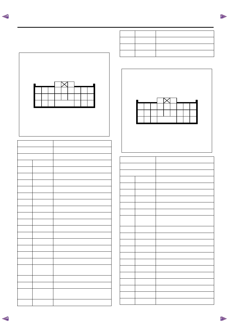
Transmission Control Module (TCM)
Connector End Views
TCM (Gray connector)
TCM (White connector)
Connector No.
C-94
Connector color
Gray
Test adapter No.
J-35616-64A
Pin No.
Wire color
Pin function
1
RED/ WHT
Battery voltage
2
YEL/ VIO
P range switch signal
3
RED
Brake pedal switch signal
4
PNK/ WHT
3rd start lamp control
5
VIO/ GRN
Keyword serial data communication
6
—
Not used
7
BLK/ RED
Engine speed signal input
8
—
Not used
9
—
Not used
10
BLK/ YEL
Vehicle speed signal output (2WD)
11
GRN/ WHT 3rd start switch signal
12
BLU/ WHT
4WD low signal output
13
—
Not used
14
—
Not used
15
—
Not used
16
RED/ WHT
Accelerator pedal position (APP)
signal input
17
BLK/GRN
3 range switch signal
18
YEL/ BLK
Diagnostic request switch
19
ORN/ BLU
Transmission oil temperature lamp
control
20
GRY/ YEL
Check trans lamp control
1
10
19
2
11
20
3
12
21
4
13
5
14
6
15
7
16
22
8
17
23
9
18
24
21
PNK
Power lamp control
22
—
Not used
23
—
Not used
24
GRN/ YEL
Power drive switch signal
Connector No.
C-95
Connector color
White
Test adapter No.
J-35616-64A
Pin No.
Wire color
Pin function
1
RED/ YEL
2-4 brake TFP switch signal
2
PNK/ BLK
2 range switch signal
3
BRN/ RED
ISS sensor signal
4
BLU
TFT sensor signal
5
BLK
Ground
6
BLU/ BLK
Low & reverse brake solenoid
control
7
BLK/ YEL
2 & 4 brake solenoid control
8
RED
High clutch solenoid control
9
WHT/ BLU
Low clutch solenoid control
10
RED/ BLK
N range switch signal
11
BLU
D range switch signal
12
YEL
Low & reverse brake TFP switch
13
YEL/ RED
OSS sensor signal
14
BLU/ BLK
TFT sensor low reference
15
—
Not used
16
—
Not used
17
BLK
TCC solenoid control
18
WHT
Ignition voltage
1
10
19
2
11
20
3
12
21
4
13
5
14
6
15
7
16
22
8
17
23
9
18
24
7A2-18 TRANSMISSION CONTROL SYSTEM (JR405E)
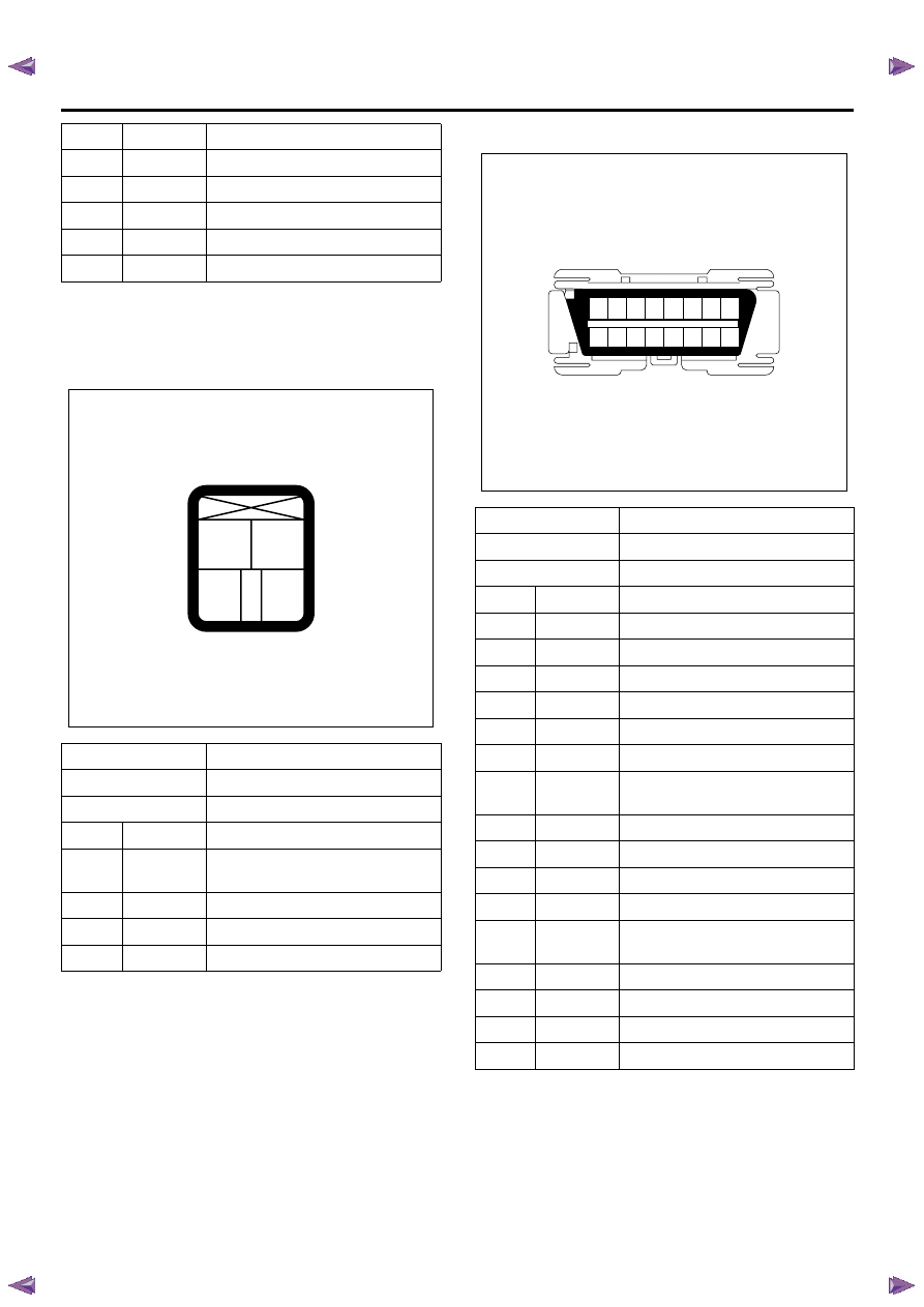
Transmission Control Connector End
Views
Brake Switch
Data Link Connector (DLC)
19
RED/ YEL
R range switch signal
20
WHT/ BLK
High clutch TFP switch signal
21
PNK/ BLU
L range switch signal
22
GRY/ RED
Ground return
23
VIO
PC solenoid control
24
WHT
Ignition voltage
Connector No.
C-44
Connector color
White
Test adapter No.
J-35616-40
Pin No.
Wire color
Pin function
1
GRN
Switch 1 (stop lamp switch) battery
voltage feed
2
RED
Switch 1 (stop lamp switch) signal
3
—
Not used
4
—
Not used
2
1
3
4
Connector No.
B-58
Connector color
Black
Test adapter No.
J-35616-2A
Pin No.
Wire color
Pin function
1
BLK/ GRN
Diagnostic request switch (ECM)
2
—
Not used
3
—
Not used
4
BLK
Ground
5
BLK
Ground
6
BLU
CAN high
7
VIO/ GRN
Keyword serial data (TCM, EHCU
[ABS module] and SRS control unit)
8
—
Not used
9
—
Not used
10
—
Not used
11
YEL/ BLK
Diagnostic request switch (TCM)
12
ORN/ WHT Diagnostic request switch (EHCU
[ABS module])
13
RED
Diagnostic request switch (SRS)
14
YEL
CAN low
15
—
Not used
16
RED/ YEL
Battery voltage
8
7
6
5
4
3
2
1
16
15
14
13
12
11
10
9
TRANSMISSION CONTROL SYSTEM (JR405E) 7A2-19
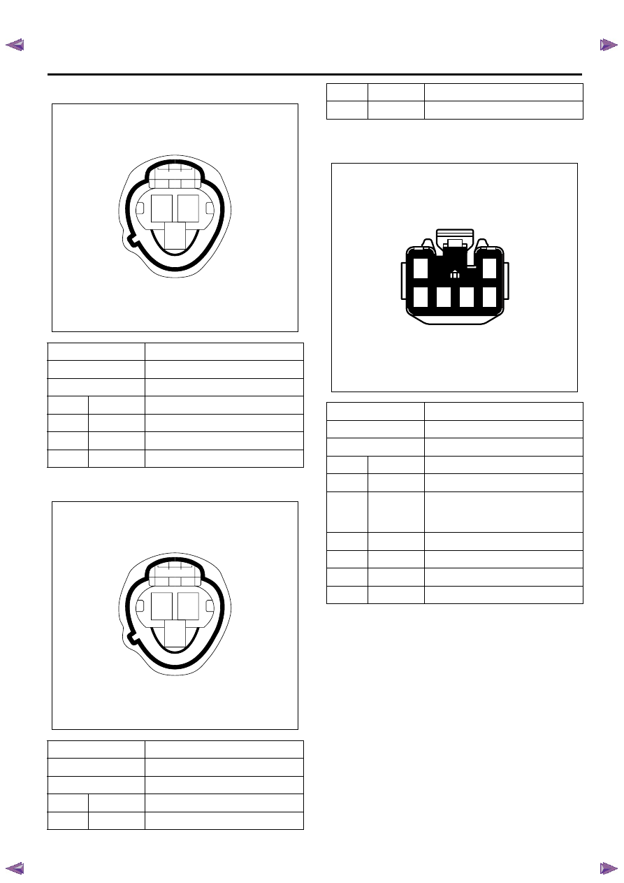
Input Shaft Speed (ISS) Sensor
Output Shaft Speed (OSS) Sensor
Power Drive/ 3rd Start Switch
Connector No.
E-31
Connector color
Gray
Test adapter No.
J-35616-
Pin No.
Wire color
Pin function
1
BRN/ RED
Sensor signal
2
WHT
Sensor ignition voltage feed
3
BLK
Sensor low reference
Connector No.
E-30
Connector color
Gray
Test adapter No.
J-35616-
Pin No.
Wire color
Pin function
1
YEL/ RED
Sensor signal
1
2
3
1
2
3
2
WHT
Sensor ignition voltage feed
3
BLK
Sensor low reference
Connector No.
B-50
Connector color
White
Test adapter No.
J-35616-33
Pin No.
Wire color
Pin function
1
GRN/ RED
Illumination lamp voltage feed
2
RED/ GRN
(TF) or
BLK (UC)
Illumination lamp ground
3
GRN/ YEL
Power drive switch signal
4
—
Not used
5
GRN/ WHT
3rd start switch signal
6
BLK
Switch ground
1
3 4 5
2
6
Нет комментариевНе стесняйтесь поделиться с нами вашим ценным мнением.
Текст