Isuzu KB P190. Manual — part 1076
7A2-20 TRANSMISSION CONTROL SYSTEM (JR405E)
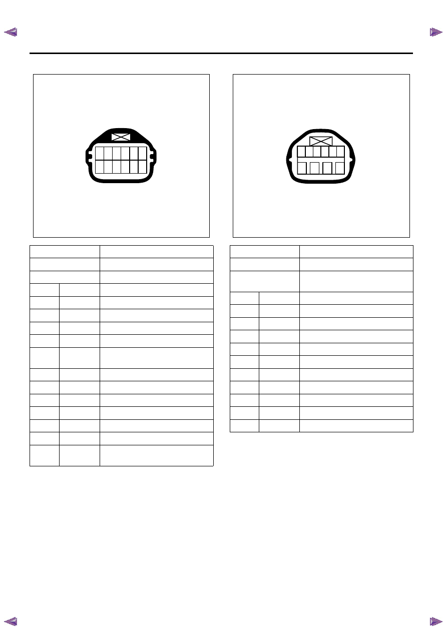
Transmission In-line Harness Connector
Transmission Range (TR) Switch
Connector No.
E-54
Connector color
Black
Test adapter No.
J-35616-64A
Pin No.
Wire color
Pin function
1
WHT/ BLK
High clutch TFP switch signal
2
BLU
TFT sensor signal
3
WHT/ BLU
Low clutch solenoid control (PWM)
4
BLK
TCC solenoid control (PWM)
5
BLU/ BLK
Low & reverse brake solenoid
control (PWM)
6
VIO
PC solenoid control
7
RED/ YEL
2-4 brake TFP switch signal
8
BLU/ BLK
TFT sensor low reference
9
BLK/ YEL
2-4 brake solenoid control (PWM)
10
RED
High clutch solenoid control (PWM)
11
GRY/ RED
Ground return
12
YEL
Low & reverse brake TFP switch
signal
RTW77ASH004001
1 2 3 4 5 6
7 8 9 10 11 12
Connector No.
E-51
Connector color
Black
Test adapter No.
J-35616-64A (pin 1 - 6)
J35616-33 (pin 7 - 10)
Pin No.
Wire color
Pin function
1
BLK/GRN
3 range switch signal
2
YEL/ VIO
P range switch signal
3
WHT
Ignition voltage feed
4
RED/ YEL
R range switch signal
5
BLU
D range switch signal
6
PNK/ BLU
L range switch signal
7
BLK/ WHT
P or N range start switch signal
8
RED/ BLK
N range switch signal
9
PNK/ BLK
2 range switch signal
10
BLK
P or N range start switch ground
RTW77ASH004101
1 2 3 4 5 6
7
8
9 10
TRANSMISSION CONTROL SYSTEM (JR405E) 7A2-21
Diagnostic Information and Procedures
Diagnostic Starting Point - Transmission Controls
Begin the system diagnosis with Diagnostic System
Check - Transmission Controls. The Diagnostic System
Check - Transmission Controls will provide the
following information:
• The identification of the control modules which
command the system.
• The ability of the control modules to communicate
through the serial data circuit.
• The identification of any stored diagnostic trouble
codes (DTCs) and the their statuses.
The use of the Diagnostic System Check -
Transmission Controls will identify the correct
procedure for diagnosing the system and where the
procedure is located.
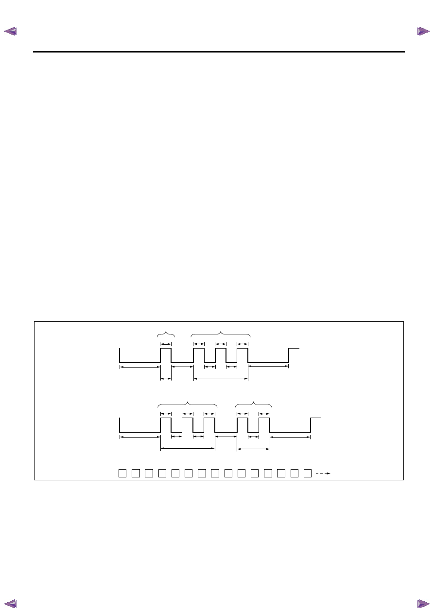
Reading Flash Diagnostic Trouble Codes (DTC)
The provision for communicating with the TCM is the
Data Link Connector (DLC). The DTC(s) stored in the
TCM memory can be read either through a hand-held
diagnostic scanner such as Tech 2 plugged into the
DLC or by counting the number of flashes of the
CHECK TRANS lamp when the diagnostic test terminal
of the DLC is grounded. The DLC terminal “11”
(diagnostic request) is pulled “Low” (grounded) by
jumped to DLC terminal “4”, which is a ground wire.
Once terminals “11” and “4” have been connected, turn
the ignition switch ON, with the engine OFF. The
CHECK TRANS lamp initially flashes 12. If more than
one DTC has been stored in the TCM's memory, the
DTCs will be output numerical order with each DTC
being displayed three times. All the stored DTCs are
flashed, then return 12 and continue to flash the DTC. If
no DTC exists, the CHECK TRANS flashes 12
continuously. The flash DTC display will continue as
long as the DLC is shorted.
Diagnostic Trouble Codes (DTC) Clear Method
If there is no scan tool, history DTCs can be cleared by
removing the ECM (B) (10A) fuse for at least 10
seconds with the ignition switch OFF.
Unit: second
13
13
13
32
32
32
12
13
13
13
32
32
32
12
12
Example: DTC 13 stored
ON
OFF
Example: DTC 32 stored
Example: DTC 13 and 32 are stored
ON
OFF
3
1
0.4
0.4
0.4
0.4
3
2
0.4
0.4
0.4
0.4
0.4
2nd digit number
1st digit number
3.2
3.2
0.4
0.4
0.4
1.2
2nd digit number
1st digit number
0.4
0.4
1.2
3.2
3.2

7A2-22 TRANSMISSION CONTROL SYSTEM (JR405E)
Diagnostic System Check - Transmission Controls
Description
The Diagnostic System Check - Transmission Controls
is an organized approach to identifying a condition that
is created by a malfunction in the electronic
transmission control system. The Diagnostic System
Check must be the starting point for any driveability
concern. The Diagnostic System Check directs the
service technician to the next logical step in order to
diagnose the concern. Understanding and correctly
using the diagnostic table reduces diagnostic time, and
prevents the replacement of good parts.
Test Description
The numbers below refer to the step numbers on the
diagnostic table.
2. Lack of communication may be because of a partial
or a total malfunction of the serial data circuit.
8. If there are other modules with DTCs set, refer to the
DTC list. The DTC list directs you to the appropriate
diagnostic procedure. If the control module stores
multiple DTCs, diagnose the DTCs in the following
order:
• Component level DTCs, such as sensor DTCs,
solenoid DTCs, actuator DTCs, and relay DTCs.
Diagnose the multiple DTCs within this category in
numerical order. Begin with the lowest numbered
DTC, unless the diagnostic table directs you
otherwise.
Diagnostic System Check Transmission Controls
Important:
• DO NOT perform this diagnostic if there is not a
driveability concern, unless another procedure
directs you to this diagnostic.
• Before you proceed with diagnosis, search for
applicable service bulletins.
• Unless a diagnostic procedure instructs you, DO
NOT clear the DTCs.
• Ensure the battery has a full charge.
• Ensure the battery cables (+) (-) are clean and
tight.
• Ensure the TCM grounds are clean, tight, and in
the correct location.
• Ensure the TCM harness connectors are clean
and correctly connected.
• Ensure the TCM terminals are clean and correctly
mating.
• If there are gear ratio DTC's (P0731, P0732,
P0733 or P0734), diagnose sensor DTCs and
solenoid DTCs first.
Diagnostic System Check - Transmission Controls
Step
Action
Value(s)
Yes
No
1
Install a scan tool.
Does the scan tool turn ON?
—
Go to Step 2
Go to Scan Tool
Does Not Power Up
2
1.
Turn ON the ignition, with the engine OFF.
2.
Attempt to establish communication with the
listed control modules.
• TCM
• Electronic hydraulic control unit (EHCU)
[ABS module] (If so equipped)
• Supplemental restraint system (SRS)
control module (If so equipped)
Does the scan tool communicate with all the listed
control modules?
—
Go to Step 3
Go to Scan Tool
Does Not
Communicate with
Keyword Device
3
Attempt to start the engine.
Does the engine start and idle?
—
Go to Step 4
Go to Engine
Cranks but Does
Not Run in engine
control section
4
Select the DTC display function for the following
control modules:
• TCM
• Engine control module (ECM)
Does the scan tool display any DTCs?
—
Go to Step 5
Go to Step 9
5
Does the scan tool other control module
communication fault DTCs?
—
Go to Applicable
DTC
Go to Step 6
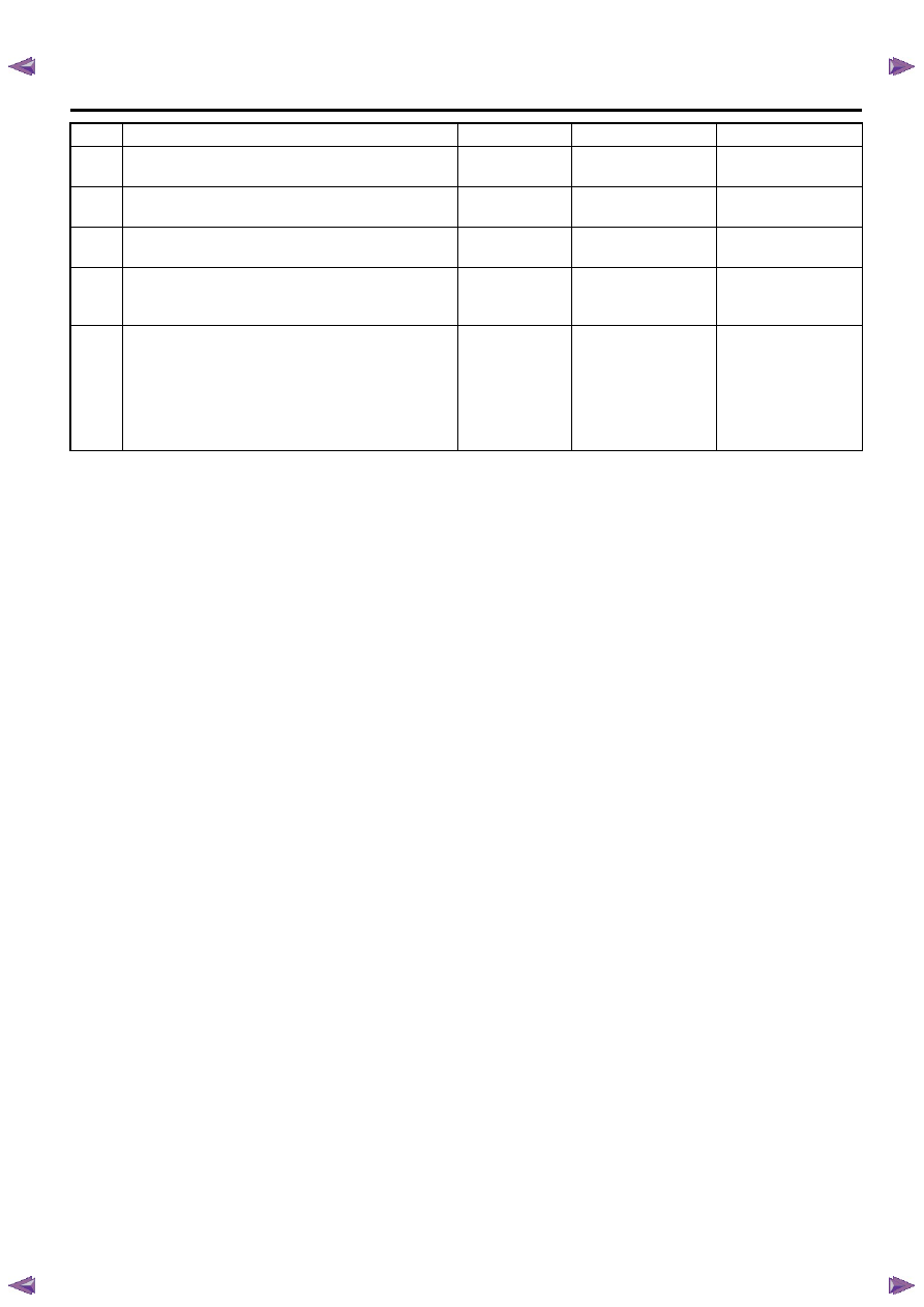
TRANSMISSION CONTROL SYSTEM (JR405E) 7A2-23
6
Does the scan tool display TCM DTC P0602?
—
Go to Applicable
DTC
Go to Step 7
7
Does the scan tool display TCM DTC P0560?
—
Go to Applicable
DTC
Go to Step 8
8
Is there any other code in any controller that has
not been diagnosed?
—
Go to Applicable
DTC
Go to Step 9
9
Is the customer's concern with the engine system?
—
Go to Diagnostic
System Check -
Engine Controls
Go to Step 10
10
Drive vehicle and verify if any engine or
transmission related driveability concern exist.
Does an engine or transmission driveability
concern exist?
—
Go to Symptoms -
Engine Controls in
engine control
section or
Symptoms
Transmission
Controls
System OK
Step
Action
Value(s)
Yes
No
Нет комментариевНе стесняйтесь поделиться с нами вашим ценным мнением.
Текст