Isuzu KB P190. Manual — part 1117
7A3-14 ON-VEHICLE SERVICE (JR405E)
Install or Connect
1. Install the shift cable toward the inside of the cabin
from the bottom of the vehicle.
2. Push the shift cable into the select lever base.
3. Connect the shift cable to the select lever.
4. Fix the shift cable to the bracket.
Install the clip on the marking on the shift cable.
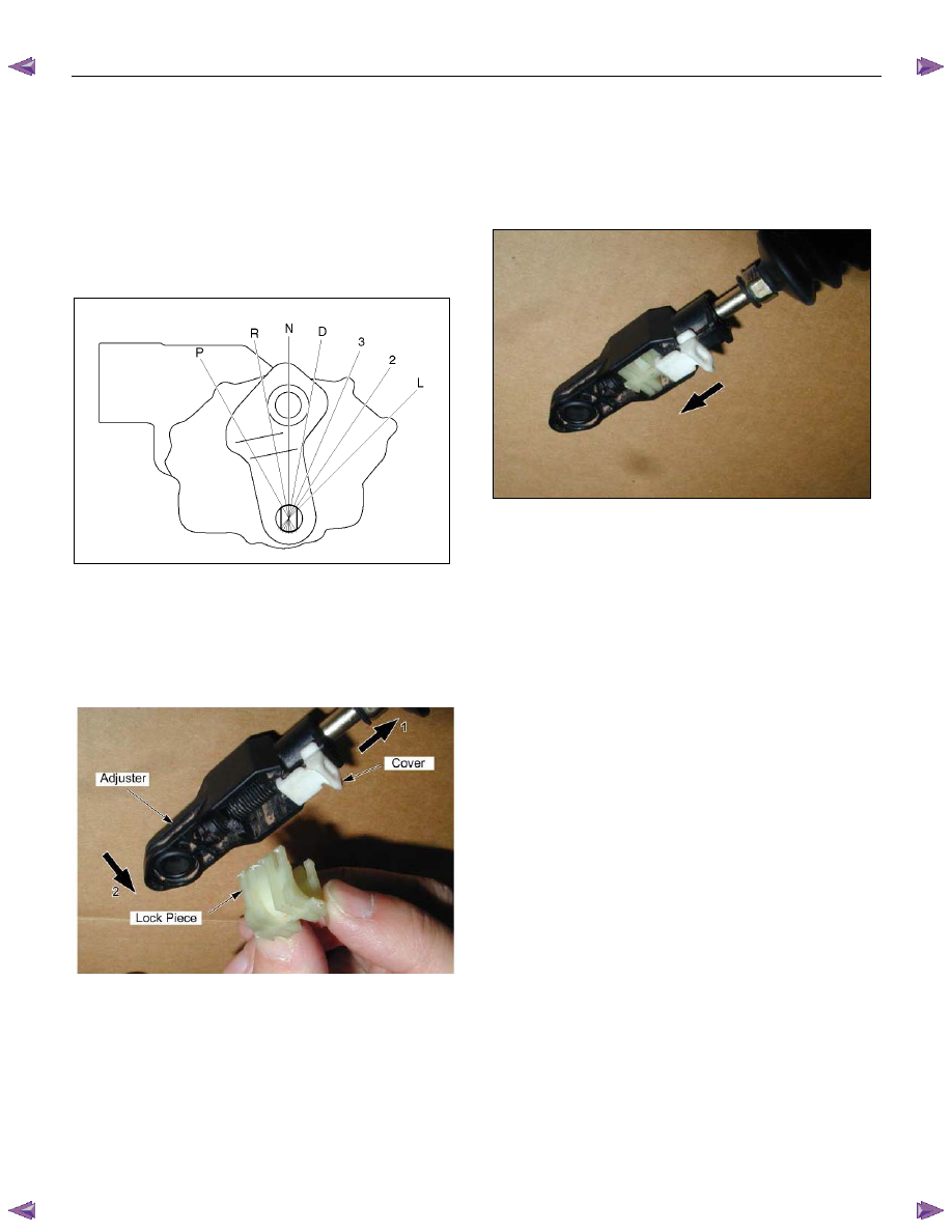
5. Check that the select lever is in the “N” position.
6. Check that the transmission is in the “N” position.
249R300002
7. Slide the cover in the direction shown by the arrow
(1).
8. Use an ordinary screwdriver to move the lock piece
from the position indicated by the arrow (2). Continue
to move the lock piece until the adjuster position
begins to change.
P1010012
9. Connect the shift cable to the manual shaft select
lever at the transmission side.
10.
Insert the lock piece to the adjuster (cable length
adjustment).
11. Slide the cover on the adjuster and secure the lock
piece.
P1010016-2
12.
Press the select lever knob button 5 times at “P”
position.
Then check that the select lever moves smoothly to
each of its positions.
13. Check that the shift position indicated by the select
lever and the actual shift position are the same.
14. Install the front console and rear console.
15. Connect the negative battery cable.
16. Remove the wheel blocks.
ON-VEHICLE SERVICE (JR405E) 7A3-15
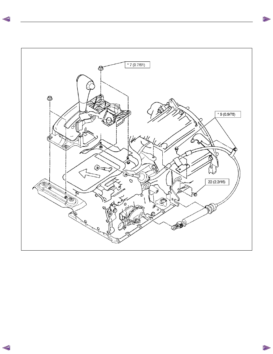
Torque Specifications
∗∗∗∗N⋅⋅⋅⋅m (kgf⋅⋅⋅⋅m/lb⋅⋅⋅⋅in)
N
⋅⋅⋅⋅m (kgf⋅⋅⋅⋅m/lb⋅⋅⋅⋅ft)
RTW77ALF000401

7A3-16 ON-VEHICLE SERVICE (JR405E)
SOLENOIDS, OIL PRESSURE SWITCH AND OIL TEMPERATURE
SENSOR
244L300003
Legend
1. High clutch oil pressure switch connector
(wire color: Gray)
2. 2-4 brake oil pressure switch connector
(wire color: Brown)
3. Low and reverse brake oil pressure switch
connector (wire color: White)
4. Low and reverse brake duty solenoid connector
(wire color: Pink and White)
5. High clutch duty solenoid connector
(wire color: Green and Gray)
6. Lock-up duty solenoid connector
(wire color: Yellow and Black)
7. 2-4 brake duty solenoid connector
(wire color: Blue and Brown)
8. Low clutch duty solenoid connector
(wire color: Orange and Black)
9. Line pressure solenoid connector
(wire color: Pink)
ON-VEHICLE SERVICE (JR405E) 7A3-17
Remove or Disconnect
1. Block the wheels.
2. Disconnect the negative battery cable.
3. Drain the fluid.
Refer to “ATF CHANGE” in this section.
4. Remove the 19 bolts and oil pan.
5. Inspect the bottom of the oil pan and strainer netting
for foreign material (clutch facing and metal
shavings).
If there is an excessive accumulation of foreign
material, the oil strainer must be replaced.
Further inspection is required to determine the
source of the foreign material.
6. Remove the harness assembly (including the oil
temperature sensor).
7. Remove the 11 bolts and the solenoid fixing plate.
8. Remove the 6 solenoids and 3 oil pressure switches.
Inspect
Oil pressure switch
Apply compressed air (390 kPa/4.0 kgf/cm
2
/57 psi) to
the oil pressure switch to check the oil pressure switch
continuity between the connector and screw.
Replace the oil pressure switch if the result of inspection
is abnormal.
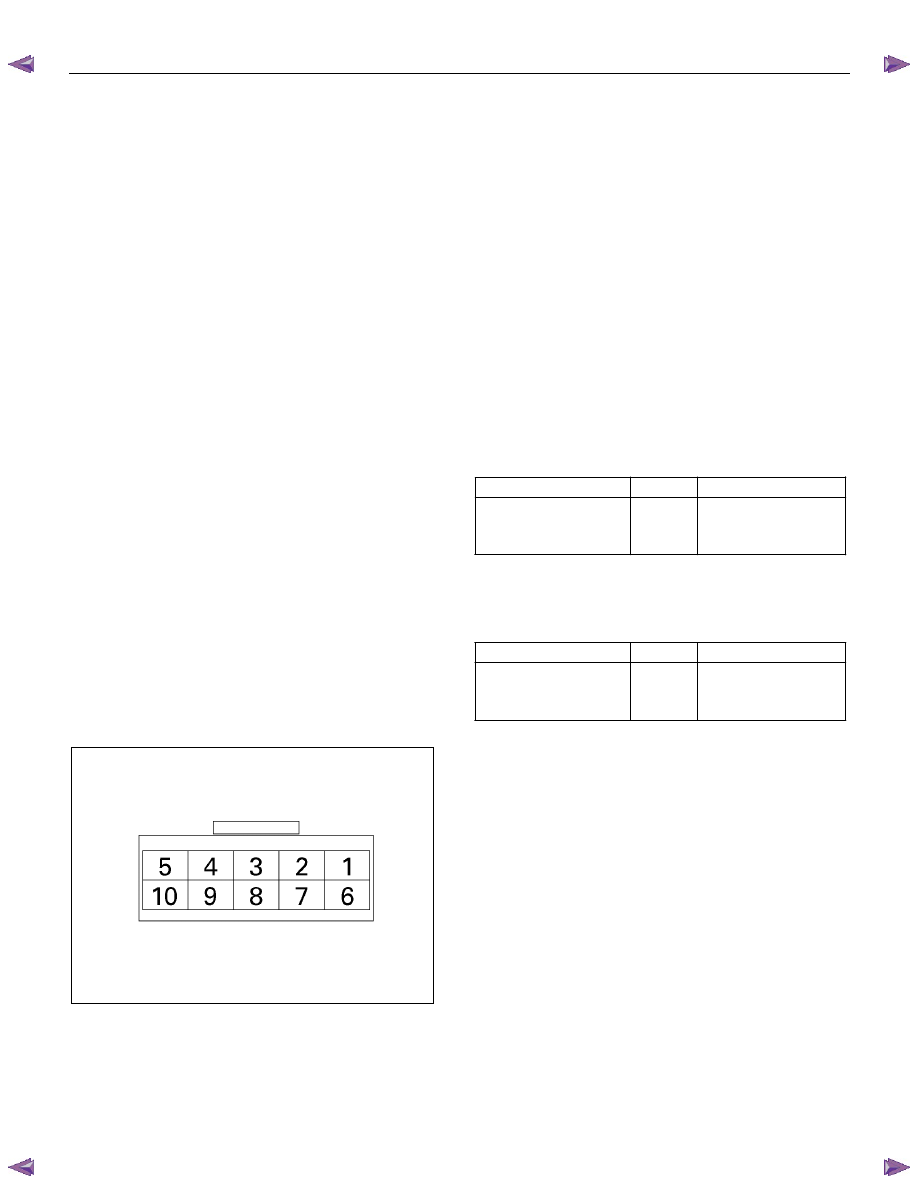
Oil temperature sensor (harness assembly)
Check the oil temperature sensor resistance between
harness terminals 7 and 6 (ground).
Oil temperature sensor resistance:
2,400~2,600 ohms (20
°°°°C)
244L300011
Solenoid
Measure the resistance of each solenoid.
Resistance:
Brown connector – 3.0~3.4 ohms (20
°°°°C)
Gray connector – 12.0~13.2 ohms (20
°°°°C)
White connector – 12.2~13.4 ohms (20
°°°°C)
Replace the solenoid if the result of inspection is
abnormal.
Install or connect
1. Install the O-rings to each of the solenoids.
2. Install the 6 solenoids and 3 oil pressure switches.
Line pressure solenoid bolt torque:
8 N·m (0.8 kgf·m/69 lb·in)
Oil pressure switch bolt torque:
4 N·m (0.4 kgf·m/35 lb·in)
3. Install the solenoid fixing plate together with the
harness brackets.
Number
Length
(Color)
Solenoid fixing plate bolt
(A)
(B)
4
7
16 mm (0.63 in) (Gold)
45 mm (1.77 in) (Silver)
Bolt torque : 8 N·m (0.8 kgf·m/69 lb·in)
4. Install the harness assembly.
5. If removed, install the oil strainer.
Number
Length
(Color)
Oil strainer bolt
(C)
(D)
9
4
13 mm (0.51 in) (Silver)
45 mm (1.77 in) (Silver)
Bolt torque : 8 N·m (0.8 kgf·m/69 lb·in)
6. Install the new gasket and oil pan.
Bolt torque : 8 N·m (0.8 kgf·m/69 lb·in)
7. Fill the fluid.
Refer to “ATF CHANGE” in this section.
8. Connect the negative battery cable.
9. Remove the wheel blocks.
Нет комментариевНе стесняйтесь поделиться с нами вашим ценным мнением.
Текст