Isuzu KB P190. Manual — part 1116
7A3-10 ON-VEHICLE SERVICE (JR405E)
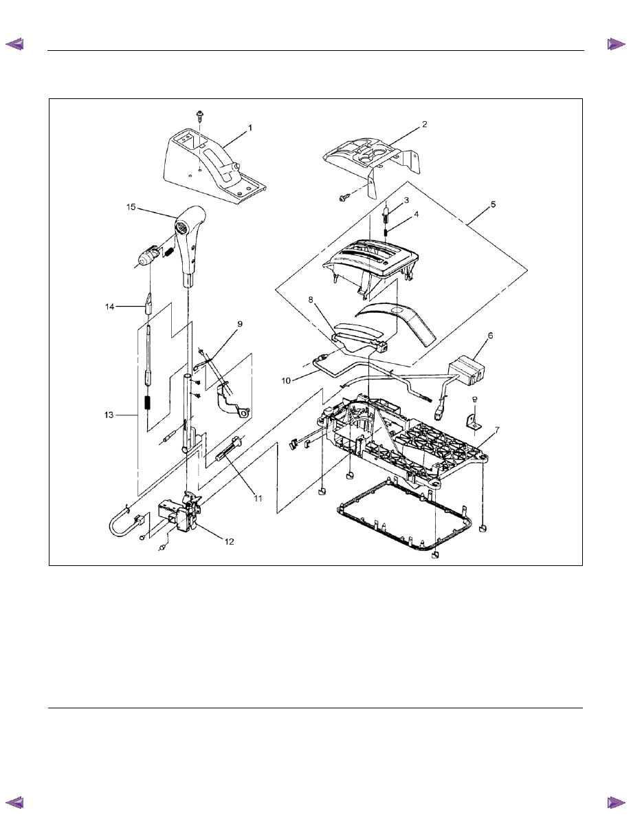
SELECT LEVER
RTW77ALF000201
Legend
1. Rear
console
2. Front
console
3. Shift lock release button
4. Shift lock button spring
5. Upper housing
6. Interlock controller
7. Base
plate
8. Position indicator housing
9. Spring
plate
10. Lamp assembly
11. Grooved pin
12. Shift lock unit
13. Lever assembly
14. Sleeve
15. Select lever knob
ON-VEHICLE SERVICE (JR405E) 7A3-11
Remove or Disconnect
1. Block the wheels.
2. Disconnect the negative battery cable.
3. Remove the rear console and the front console.
4. Remove the 2 screws fixing the select lever knob.
5. Remove the knob together with the knob button and
spring from the lever.
6. Turn the sleeve counterclockwise to remove it.
Make a note of the number of turns required to free
the sleeve.
7. Remove the harness connectors from the base
plate.
8. Remove the upper housing (held in place by 4
latched fasteners).
9. Remove the lamp assembly by turning it
counterclockwise.
10. Remove the spring plate.
11. Remove the grooved pin.
12. Disconnect the shift cable from the select lever.
13. Remove the lever assembly by pressing the rod
down (lever in N position).
14. Remove the harness connectors from the shift lock
unit, then remove the shift lock unit.
15. Remove the interlock controller.
16. If the replacement of shift lock release button or
shift lock button spring is required, remove the
position indicator housing, the shift lock button
spring and shift lock release button can be
removed.
Install or Connect
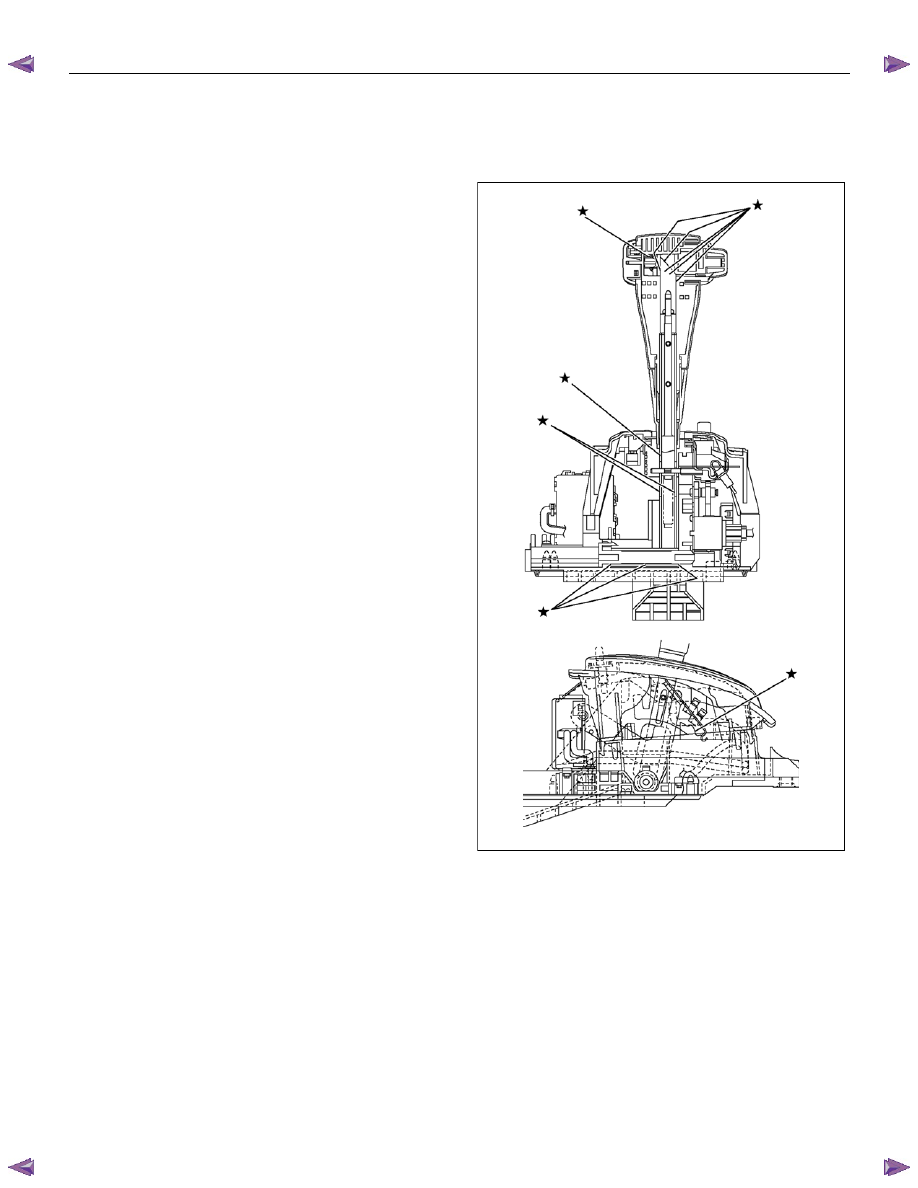
NOTE
Apply MULTEMP No. 2 grease (or equivalent) to the
select lever. Refer to the illustration.
RTW77ALH000201
1. Install the interlock controller.
2. Install the shift lock unit and connect the harness to
the shift lock unit.
3. Install the lever assembly to the base plate.
a. Insert and secure the shaft and connect the
cable.
b. Insert pawled end of the shaft into the base plate
hole.
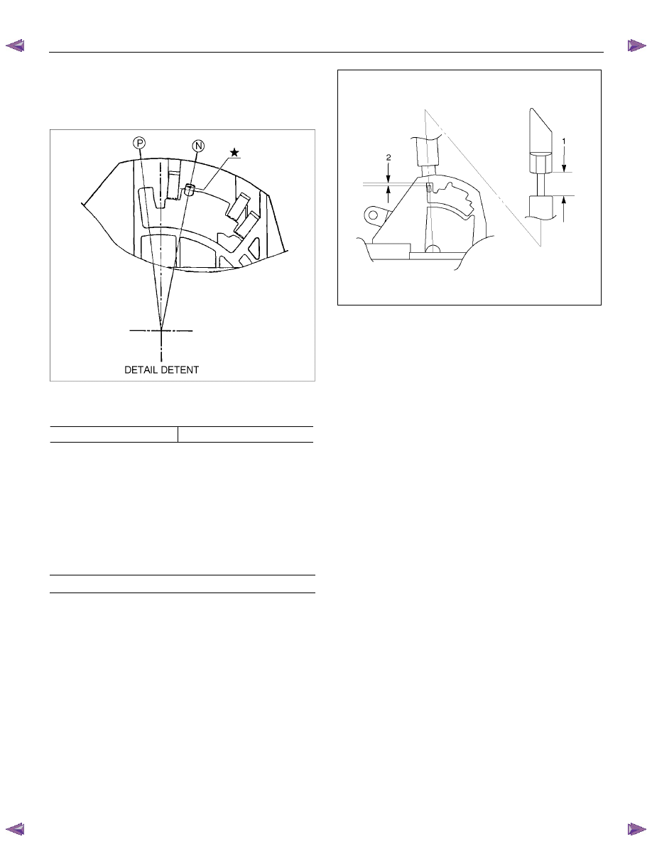
c. Insert the detent pin of the shaft into detent
aperture (lever assembly in N position).
d. Install the grooved pin.
7A3-12 ON-VEHICLE SERVICE (JR405E)
4. Install the spring plate.
a. Insert the detent pin into the base plate detent
groove until it touches the front wall (lever
assembly in N position).
RTW37ASH001001
b. Stack the short spring plate and tighten the
screws to the specified torque.
Screw torque
2 N
⋅m (0.2kgf⋅m/17 lb⋅in)
c. Check that the detent pin moves smoothly in the
detent groove (shift knob temporarily installed).
5. Temporarily install the sleeve.
6. Move the lever to the “P” position.
7. Adjust the clearance (2) between the detent plate
and the pin by moving the select lever knob sleeve
(1).
Detent plate and pin clearance
mm(in)
0.2 - 1.0 (0.01 - 0.04)
255R300002
8. Install the lamp assembly to the lamp socket.
a. Align the recessed portion of the lamp socket with
the protruding portion of the lamp assembly.
b. Insert the lamp assembly into the lamp socket
and rotate it 90 degrees clockwise.
9. Remove the sleeve and move the lever to the “N”
position.
10. Install the upper housing. Make sure that the 4
latched fasteners are securely closed.
11. Attach the harness connectors to the base plate.
12. Install the sleeve (rotate the sleeve clockwise the
same number of turns it was rotated
counterclockwise at disassembly).
13. Install the knob, the knob button, and the knob
spring.
14. Install the 2 screws securing the knob and tighten
them to the specified torque.
Screw torque: 2 N
⋅m (0.2kgf⋅m/17 lb⋅in)
ON-VEHICLE SERVICE (JR405E) 7A3-13
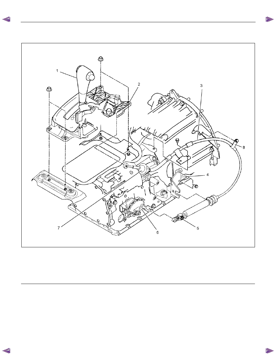
SHIFT CABLE
RTW77ALF000301
Legend
1. Select
lever
2. Select lever base
3. Shift
cable
4. Bracket
5. Adjuster
6. Manual shaft select lever
7. Shift cable retaining pawl
8. Clip
Remove or Disconnect
1. Block the wheels.
2. Disconnect the negative battery cable.
3. Move the select lever to the “N” position.
4. Remove the rear console and front console.
5. Disconnect the shift cable from the select lever.
6. Press on the shift cable retaining pawl to remove the
cable from the select lever base.
7. Disconnect the shift cable from the transmission
side.
8. Remove the shift cable from the bracket.
9. Pull the shift cable free from the bottom of the
vehicle.
Нет комментариевНе стесняйтесь поделиться с нами вашим ценным мнением.
Текст