Isuzu KB P190. Manual — part 491
ENGINE CONTROL SYSTEM (4JK1/4JJ1) 6E-347
Repair Instructions
Engine Control Module (ECM)
Replacement
Description
The following A - G steps provide an overview
procedure to replace and reprogram an ECM. Each A -
G steps is explained further in this section.
A. Recoding Fuel Injector ID Code
Each fuel injector is designated with 24 hexadecimal
characters (0 - 9 or A - F) that MUST be programmed
into the ECM for correct engine fueling for each specific
cylinder. These characters can be retrieved in one of
following places:
Retrieving the Fuel Injector ID Code Data from the
ECM
The current fuel injector ID code data can be retrieved
with a scan tool. If the old ECM cannot be
communicated with a scan tool, go to the next
procedure.
1. Install a scan tool.
2. Turn ON the ignition, with the engine OFF.
3. Select Diagnostics > appropriate vehicle
identification > 4JK1 or 4JJ1 > Programming >
Injector ID Code.
4. Record 24 digits of each fuel injector ID code.
5. After complete the recording, turn OFF the scan
tool.
6. Turn OFF the ignition.
Retrieving the Fuel Injector ID Code Data with a
Non-communicating ECM
If a scan tool does not communicate, the fuel injector ID
codes must be recorded from the factory affixed label
on the cylinder head cover or each fuel injector harness
connector housing.
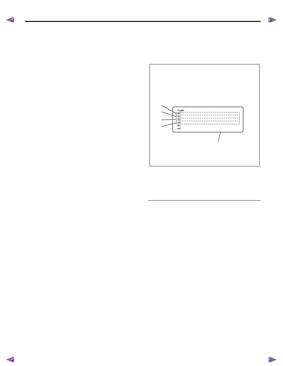
Recording from the label on cylinder head cover
Notice: Only perform this procedure if the fuel injectors
are not being replaced in the past.
1. Record all numbers of each cylinder on the label.
Legend
1. Cylinder #1 fuel injector ID code
2. Cylinder #2 fuel injector ID code
3. Cylinder #3 fuel injector ID code
4. Cylinder #4 fuel injector ID code
5. Injector ID code label
Recording from each fuel injector
1. Disconnect each fuel injector harness connector.
A.
Record the fuel injector ID codes manually from the old
ECM.
B.
Reset the immobilizer security information in the old
ECM. (If so equipped)
C.
Replace the old ECM with the new ECM.
D.
Program the immoblizer security information into the
new ECM. (If so equipped)
E.
Program the latest software and calibrations into the
new ECM using the Service Programming System
(SPS).
F.
Program the recorded fuel injector ID codes and the
vehicle identification number (VIN) into the ECM using
a scan tool programming function.
G.
Perform the fuel supply pump relearn procedure by
allowing the engine to idle in Park or Neutral until
normal operating temperature is achieved.
RTW76ESH002501
1
2
3
4
5
4JJ1
5F
5F
5F
5F
05
F8
DE
DE
00
00
E6
F5
FB
F8
D2
DB
00
00
DC
ED
F7
E7
DE
E8
08
02
00
02
F5
FC
F4
F4
19
EC
CB
DE
FF
ED
CA
D1
04
EE
E3
EA
49
B9
A1
B9
SAMPLE
6E-348 ENGINE CONTROL SYSTEM (4JK1/4JJ1)
2. Record all numbers of each cylinder on the
harness connector housing. The correct order for
the fuel injector ID codes of the following
illustration is as follows:
5F 05 00 FB 00 F7 08 F5 19 FF 04 49
Legend
1. Fuel injector ID code
2. Fuel injector
B. Resetting Immobilizer Security Information (If so
equipped)
Reset immobilizer security information in the old ECM.
Refer to Resetting and Programming Guidelines in
immobilizer section. If the old ECM cannot be
communicated with a scan tool, go to the next produce.
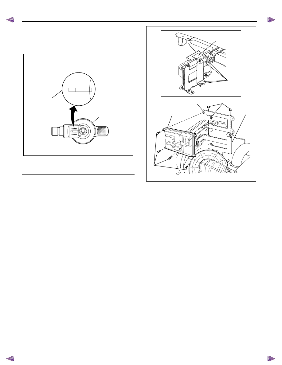
C. Removal and Installation
Removal Procedure
1. Disconnect the negative battery cable.
2. Loosen bolts (7) and remove the ECM cover (6). (If
so equipped)
3. Disconnect the ECM harness connectors.
4. Loosen nuts (1) and remove the ECM with bracket
(2) from the base bracket (3).
5. Loosen bolts (4) and remove the ECM (5).
Installation Procedure
1. Install the ECM (5) to the bracket (2) and tighten
bolts (4).
2. Install the ECM with bracket (2) to the base
bracket (3) and tighten nuts (1).
3. Connect the ECM harness connectors.
4. Install the ECM cover (6) and tighten bolts (7).
5. Connect the negative battery cable.
D. Programming Immobilizer Security Information
(If so equipped)
Programming immobilizer security information into the
ECM. Refer to Resetting and Programming Guidelines
in immobilizer section.
E. Programming Software and Calibrations
Program latest software/ calibrations if released. Refer
to Service Programming System (SPS) Description and
SPS (Remote Procedure) or SPS (Pass-Thru
Procedure) in this section.
F. Programming Fuel Injector ID Codes and VIN
1. Install a scan tool.
2. Turn ON the ignition, with the engine OFF.
3. Select Diagnostics > appropriate vehicle
identification > 4JK1 or 4JJ1 > Programming >
Program ECU.
RTW76ESH002601
5F 05 00
FB 00 F7
SAMPLE
08 F5 19
FF 04 49
2
1
RTW76EMH000301
5
1
2
3
4
6
7
ENGINE CONTROL SYSTEM (4JK1/4JJ1) 6E-349
4. In order to get programming approval, the on-
screen displays a message to user. Get
programming approval from the TIS 2000 using
the following procedure:
a. Connect a scan tool to the terminal that
installed TIS 2000 with the latest software and
the hardware key is plugged into port.
b. Turn ON the scan tool and keep at title screen.
c. Launch the TIS application.
d. Select the Security Access at the main screen.
e. Highlight the “Tech 2” on the Diagnostic Tool
Selection screen and click “Next”.
f. Click “Close” on the Security Access Enabled
screen.
g. Turn OFF the scan tool.
h. Disconnect the scan tool from the terminal.
5. Install a scan tool to the vehicle.
6. Turn ON the ignition, with the engine OFF.
7. Select Diagnostics > appropriate vehicle
identification > 4JK1 or 4JJ1 > Programming >
Program ECU.
8. Verify the VIN on the screen if programmed at
previously described SPS. If not programmed or
incorrect VIN, input correct VIN.
9. Input 24 digits of each fuel injector ID code.
10. After complete the programming, turn OFF the
ignition for 30 seconds.
11. Start the engine and let idle.
12. Inspect for a proper engine running condition and
for no DTC's. Refer to the Diagnostic System
Check - Engine Controls if needed.
G. Supply Pump Relearn
1. Install a scan tool.
2. Start the engine and let idle until engine coolant
temperature reads 65
°C (149°F) or higher while
observing the Supply Pump Status parameter with
a scan tool. The scan tool parameter changes
status Not Learn > Learning > Learned.
3. If the ECM has correctly learned the fuel supply
pump current adjustment, the Supply Pump Status
parameter on the scan tool will repeatedly indicate
Learning and Learned.
Service Programming System (SPS)
Description
The service programming system (SPS) allows a
technician to program a control module through the
data link connector (DLC). The information transfer
circuit that is used at the DLC is the same serial data
circuit used by the scan tool for retrieving DTCs,
displaying data, clearing DTCs etc. This procedure
offers the ability to install software/ calibrations
matched to a particular vehicle.
Most control modules have two types of memory. The
software/ calibrations reside in the flash memory. The
two types of memory are listed below:
• Electrically Erasable Programmable Read Only
Memory (EEPROM)
This type of memory allows selected portions of
memory to be programmed while other portions
remain unchanged.
Certain learned values reside in the EEPROM,
such as:
- The vehicle identification number (VIN)
- The software/ calibrations identification
numbers
- The control module security information
• Flash Read Only Memory-Flash Memory
Flash memory has increased memory storage
capacity. During programming, all information
within this type of memory is erased, and then
replaced with entirely new information.
Service Programming Methods
The two methods of programming an ECM are listed
below:
• Remote Programming
• Pass Thru Programming
For information on programming an ECM using one of
the methods listed above, refer to Service
Programming System (SPS) (Remote Procedure) or
Service Programming System (SPS) (Pass-Thru
Procedure).
Before Programming a Control Module
Important: DO NOT program an existing ECM with the
identical software/ calibration package. This procedure is not
a short cut to correct the driveability condition. This is an
ineffective repair. An ECM should only be programmed when
the following occurs:
• When a service procedure instructs you to replace
the ECM.
• An updated software/ calibrations is released.
Ensure that the following conditions are met before
programming an ECM:
• The scan tool PCMCIA card is programmed with
the latest software.
• The TIS 2000 is installed with the latest software.
6E-350 ENGINE CONTROL SYSTEM (4JK1/4JJ1)
• The hardware key is plugged into the computer
port.
• Vehicle system voltage:
- There are no charging system concerns. All
charging system concerns must be repaired
before programming the ECM.
- The battery voltage is greater than 12 volts but
less than 16 volts. The battery must be fully
charged before programming the ECM.
- A battery charger is NOT connected to the
vehicles battery. Incorrect system voltage or
voltage fluctuations from a battery charger may
cause programming failure or ECM damage.
- Turn OFF or disable any system that may put a
load on the vehicles battery. Turn OFF or
disable systems such as:
◊ Heating, ventilation, and air conditioning
(HVAC) systems
◊ Headlights
◊ Room lights
◊ Accessory equipment
• The ignition switch is in the proper position. The
scan tool prompts you to turn ON the ignition, with
the engine OFF. DO NOT change the position of
the ignition switch during the programming
procedure unless instructed to do so.
• All tool connections are secure:
- The RS-232 cable
- The connection at the DLC
- The voltage supply circuits
• DO NOT disturb the tool harnesses while
programming. If an interruption occurs during the
programming procedure, programming failure or
ECM damage may occur.
• If you are performing the Pass-Thru programming
procedure using a notebook computer without the
power cord, ensure that the internal battery is fully
charged.
Service Programming System (SPS)
(Remote Procedure)
Notice: Some module will not accept SPS remote
procedure using 10MB PCMCIA card. In such case,
use 32MB PCMCIA card or SPS pass-thru procedure.
The Remote SPS method is a three-step process that
involves the following procedures:
1. Connecting the scan tool to the vehicle and
obtaining the information from the ECM.
2. Connecting the scan tool to the terminal and
downloading a new calibration file from the
terminal into the scan tool memory.
3. Reconnecting the scan tool to the vehicle and
uploading the new calibration file into the ECM.
Performing the Remote Procedure
1. Connect a scan tool to the vehicle and obtain the
ECM information using the following procedure:
Notice: Ensure the ECM is installed in the vehicle and
the battery is fully charged before programming.
a. Install a scan tool.
b. Turn ON the ignition, with the engine OFF.
c. Select Service Programming System (SPS) >
Request Info.
d. If there is already stored in the scan tool, the
existing data is displayed on the screen. The
scan tool asks user to keep existing data "Keep
Data" or "Continue" to request new vehicle
information from the ECM. If there is no data in
the scan tool, it will immediately start vehicle
identification.
e. Select the vehicle description by following the
on-screen instructions based on stamped VIN
or affixed VIN plate on the vehicle.
f. During obtaining information, the scan tool is
receiving information from all modules at the
same time. But only ECM information is
displayed on the screen.
g. Turn OFF all accessories and press "Okay".
h. Verify that the correct VIN is displayed on the
scan tool. If the VIN is incorrect or no VIN,
record the correct VIN.
2. Turn OFF the ignition.
3. Turn OFF the scan tool and disconnect from the
vehicle.
4. Transfer the data from the terminal to the scan tool
using the following procedure:
Notice: The TIS supports service programming with
the Tech 2 scan tool only.
a. Connect the scan tool to the terminal.
b. Launch the TIS application.
c. Select the Service Programming System at the
main screen.
d. Highlight the following information on the Select
Diagnostic Tool and Programming Process
screen, then click "Next".
• Select Diagnostic Tool - Tech 2
• Select Programming Process - Identify
whether an existing ECM is being
reprogrammed or an ECM is being replaced
with a new one
• Select ECU Location - Vehicle
e. Verify the connections on the Preparing for
Communication screen, then click "Next".
f. Verify the VIN on the Validate Vehicle
Identification Number (VIN) screen, then click
"Next".
Нет комментариевНе стесняйтесь поделиться с нами вашим ценным мнением.
Текст