Isuzu KB P190. Manual — part 1420

SUPPLEMENTAL RESTRAINT SYSTEM 9A-45
Special Tools
WARNING: TO AVOID DEPLOYMENT WHEN
TROUBLESHOOTING THE SRS, DO NOT USE
ELECTRICAL TEST EQUIPMENT SUCH AS A
BATTERY–POWERED OR AC–POWERED
VOLTMETER, OHMMETER, ETC., OR ANY TYPE
OF ELECTRICAL EQUIPMENT OTHER THAN THAT
SPECIFIED IN THIS MANUAL. DO NOT USE AN
UNPOWERED PROBE–TYPE TESTER.
INSTRUCTIONS IN THIS MANUAL MUST BE
FOLLOWED CAREFULLY, OTHERWISE
PERSONAL INJURY MAY RESULT.
5-8840-2421-0 SRS Driver/Passenger Load
Tool
901RS146
The SRS Driver/Passenger Load Tool 5-8840-2421-0
is used only when called for in this section. It is used
as a diagnostic aid and safety device to prevent
inadvertent air bag assembly deployment.
The load tool has three yellow connectors attached to
its case.
The three small connectors are electrically functional
and serve as resistive load substitutions.
No more than two connectors are used at any time.
One of the small connectors is used to substitute for
the load of the driver air bag assembly when it is
connected at the top of the column to the SRS coil
assembly. Another small connector is used to
substitute for the load of the driver air bag assembly
and the SRS coil assembly when it is connected at the
base of the column to the SRS wiring harness. The
third small connector is used to substitute for the load
of the passenger air bag assembly when connected to
the passenger air bag assembly harness connector.
By substituting the resistance of the load tool when
called for, a determination can be made as to whether
an inflator circuit component is causing system
malfunction and which component is causing the
malfunction. The load tool should be used only when
specifically called for in the diagnostic procedures.
5-8840-0366-0 DMM
901RS163
The 5-8840-0366-0 DMM is the preferred DMM for use
in SRS diagnosis and repair. No other DMMs are
approved for SRS diagnosis and repair.
Scan Tool
901RW176
9A-46 SUPPLEMENTAL RESTRAINT SYSTEM
The Tech 2 is used to read and clear SRS Diagnostic
Trouble Codes (DTCs). Refer to the Tech 2 Operators
Manual for specific information on how to use the Tech
2.
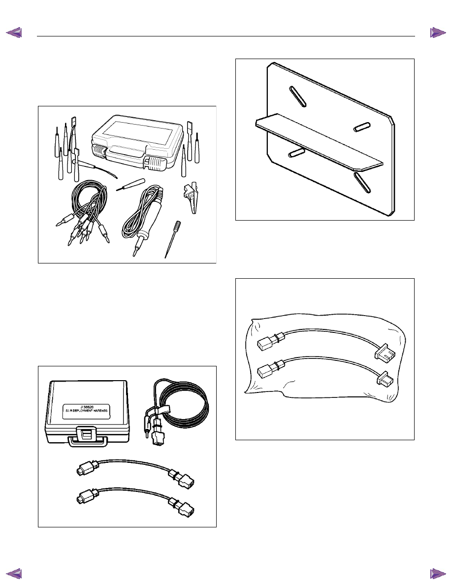
5-8840-2835-0 Connector Test Adapter Kit
AAW0Z0SH020501
The 5-8840-2835-0 Connector Test Adapter Kit must
be used whenever a diagnostic procedure requests
checking or probing a terminal. Using the appropriate
adapter will ensure that no damage to the terminal will
occur from the DMM probe, such as spreading or
bending. The adapter will also give an idea of whether
contact tension is sufficient, helping to find an open or
intermittent open due to poor terminal contact.
5-8840-2468-0 SRS Deployment Tool
901RW106
The 5-8840-2468-0 SRS Deployment Tool must be
used for deployment of the undeployed air bag.
5-8840-2420-0 SRS Deployment Fixture
901RV056
The 5-8840-2420-0 SRS Deployment Fixture must be
used for deployment of the undeployed passenger
side air bag.
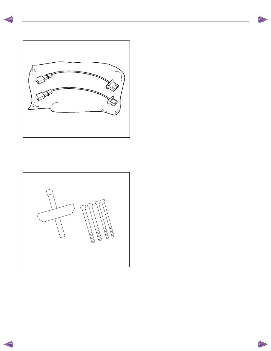
5-8840-2796-0 SRS Adapter for Load Tool
901RW107
The 5-8840-2796-0 SRS Adapter for Load Tool must
be used with the 5-8840-2421-0 SRS
Driver/Passenger Load Tool.
SUPPLEMENTAL RESTRAINT SYSTEM 9A-47
5-8840-2795-0 SRS Adapter for
Deployment Tool
901RW107
The 5-8840-2795-0 SRS Adapter for Deployment Tool
must be used with 5-8840-2468-0 SRS Deployment
Tool.
5-8521-0016-0 Steering Wheel remover
LNW28BSH003101

RESTRAINT CONTROL SYSTEM 9A1-1
SECTION 9A1
RESTRAINT CONTROL SYSTEM
TABLE OF CONTENTS
PAGE
Service Precaution . . . . . . . . . . . . . . . . . . . . . . . . . . . . . ...9A1- 2
Diagnosis Information . . . . . . . . . . . . . . . . . . . . . . . . . . . . .9A1- 3
Diagnostic Procedures . . . . . . . . . . . . . . . . . . . . . . . . . . . . 9A1- 3
Diagnostic Codes . . . . . . . . . . . . . . . . . . . . . . . . . . . . . . .9A1- 3
How To Read Trouble Codes . . . . . . . . . . . . . . . . . . . . . . . . . ..9A1- 3
How To Clear Trouble Codes . . . . . . . . . . . . . . . . . . . . . . . . . ..9A1- 3
Scan Tool Diagnostics . . . . . . . . . . . . . . . . . . . . . . . . . . . . .9A1- 3
Basic Knowledge Required . . . . . . . . . . . . . . . . . . . . . . . . . . .9A1- 4
Basic Electrical Circuits . . . . . . . . . . . . . . . . . . . . . . . . . . . ..9A1- 4
"Flash Code" Diagnostics . . . . . . . . . . . . . . . . . . . . . . . . . . ..9A1- 4
DATA LIST (Tech2) . . . . . . . . . . . . . . . . . . . . . . . . . . . . . ...9A1- 5
Diagnostic Trouble Codes . . . . . . . . . . . . . . . . . . . . . . . . . . ...9A1- 6
System Schematic . . . . . . . . . . . . . . . . . . . . . . . . . . . . . ...9A 1- 7
SRS Diagnostic System Check . . . . . . . . . . . . . . . . . . . . . . . . ...9A1- 7
Chart A SRS control unit Integrity Check. . . . . . . . . . . . . . . . . . . . ...9A1- 10
Chart B "SRS" Warning Lamp Comes "ON" Steady. . . . . . . . . . . . . . . . ..9A1- 12
Chart C "SRS" Warning Lamp Does Not Come "ON" Steady . . . . . . . . . . . . ..9A1-14
DTC B0015 (Flash Code 15) Passenger Air Bag Squib Circuit High Resistance . . . . ...9A1-17
DTC B0016 (Flash Code 16) Passenger Air Bag Squib Circuit Low Resistance . . . . . .9A1-20
DTC B0018 (Flash Code 18) Passenger Air Bag Squib Circuit Short to GND . . . . . . .9A1-23
DTC B0019 (Flash Code 19) Passenger Air Bag Squib Circuit Short to Battery
Voltage . . . . . . . . . . . . . . . . . . . . . . . . . . . . . . . . . . ..9A1- 26
DTC B0021 (Flash Code 21) Driver Air Bag Squib Circuit High Resistance. . . . . . . 9A1-28
DTC B0022 (Flash Code 22) Driver Air Bag Squib Circuit Low Resistance. . . . . . . .9A1-31
DTC B0025 (Flash Code 25) Driver Air Bag Squib Circuit Short to GND . . . . . . . . 9A1-34
DTC B0026 (Flash Code 26) Driver Air Bag Squib Circuit Short to Battery
Voltage . . . . . . . . . . . . . . . . . . . . . . . . . . . . . . . . . . ..9A1- 37
Нет комментариевНе стесняйтесь поделиться с нами вашим ценным мнением.
Текст