Isuzu KB P190. Manual — part 1421

9A1-2 RESTRAINT CONTROL SYSTEM
Service Precaution
WARNING: THIS VEHICLE HAS A SUPPLEMENTAL
RESTRAINT SYSTEM (SRS). REFER TO THE SRS
COMPONENT AND WIRING LOCATION VIEW IN
ORDER TO DETERMINE WHETHER YOU ARE
PERFORMING A SERVICE ON OR NEAR THE SRS
COMPONENTS OR THE SRS WIRING. WHEN YOU
ARE PERFORMING A SERVICE ON OR NEAR THE
SRS COMPONENTS OR THE SRS WIRING, REFER
TO THE SRS SERVICE INFORMATION. FAILURE TO
FOLLOW WARNINGS COULD RESULT
IN
POSSIBLE AIR BAG DEPLOYMENT, PERSONAL
INJURY, OR OTHERWISE UNNECESSARY SRS
SYSTEM REPAIRS.
CAUTION: Always use the correct fastener in the
proper location. When you replace a fastener, use
ONLY the exact part number for that application.
ISUZU/GM will call out those fasteners that require
a replacement after removal. ISUZU/GM will also
call out the fasteners that require thread lockers or
thread sealant. UNLESS OTHERWISE SPECIFIED,
do not use supplemental coatings (paints, greases,
or other corrosion inhibitors) on threaded fasteners
or fastener joint interfaces. Generally, such
coatings adversely affect the fastener torque and
the joint clamping force, and may damage the
fastener. When you install fasteners, use the
correct tightening sequence and specifications.
Following these instructions can help you avoid
damage to parts and systems.
DTC B0029 (Flash Code 29) Passenger pretensioner sqib Circuit High
Resistance . . . . . . . . . . . . . . . . . . . . . . . . . . . . . . . . . 9A1-40
DTC B0031 (Flash Code 31) Passenger Pretensioner Squib Circuit Low
Resistance . . . . . . . . . . . . . . . . . . . . . . . . . . . . . . . . . 9A1-43
DTC B0033 (Flash Code 33) Passenger Pretensioner Squib Circuit Short to GND . . . . 9A1-46
DTC B0034 (Flash Code 34) Passenger Pretensioner Squib Circuit Short to
Battery Voltage . . . . . . . . . . . . . . . . . . . . . . . . . . . . . . . .9A1-49
DTC B0041 (Flash Code 41) Driver Pretensioner Squib Circuit High Resistance. . . . ...9A1-51
DTC B0042 (Flash Code 42) Driver Pretensioner Squib Circuit Low Resistance . . . . ...9A1-54
DTC B0045 (Flash Code 45) Driver Pretensioner Squib Circuit Short to GND . . . . . . 9A1-57
DTC B0046 (Flash Code 34) Driver Pretensioner Squib Circuit Short to Battery
Voltage . . . . . . . . . . . . . . . . . . . . . . . . . . . . . . . . . . ..9A1-60
DTC B0051 (Flash Code 51) Air Bag Squib Circuit Activated (Crash) . . . . . . . . . .9A1-62
DTC B0052 (Flash Code 52) Pretensioner Squib Circuit Activated (Crash) . . . . . . ...9A1-64
DTC B0055 (Flash Code 55) Vehicle Variant Missing . . . . . . . . . . . . . . . . 9A1-66
DTC B0061 (Flash Code 61) Warning Lamp Circuit Failure . . . . . . . . . . . . . ..9A1-68
DTC B0062 (Flash Code 62) Battery Voltage Too High . . . . . . . . . . . . . . . 9A1-71
DTC B0063 (Flash Code 63) Battery Voltage Too Low . . . . . . . . . . . . . . . .9A1-73
DTC B0071 (Flash Code 71) SRS Control Unit Internal Fault. . . . . . . . . . . . . 9A1-75

RESTRAINT CONTROL SYSTEM 9A1-3
Diagnostic Information
CAUTION: When fasteners are removed, always
reinstall them at the same location from which they
were removed. If a fastener needs to be replaced,
use the correct part number fastener for that
application. If the correct part number fastener is
not available, a fastener of equal size and strength
(or stronger) may be used. Fasteners that are not
reused, and those requiring thread locking
compound, will be called out. The correct torque
value must be used when installing fasteners that
require it. If the above conditions are not followed,
parts or system damage could result.
Diagnostic Procedures
WARNING: TO AVOID DEPLOYMENT WHEN
TROUBLESHOOTING THE SRS, DO NOT USE
ELECTRICAL TEST EQUIPMENT SUCH AS A
BATTERY-POWERED OR AC-POWERED
VOLTMETER, OHMMETER, ETC., OR ANY TYPE OF
ELECTRICAL EQUIPMENT OTHER THAN THAT
SPECIFIED IN THIS MANUAL. DO NOT USE A NON-
POWERED, PROBE-TYPE TESTER.
INSTRUCTIONS IN THIS MANUAL MUST BE
FOLLOWED CAREFULLY, OTHERWISE PERSONAL
INJURY MAY RESULT.
The diagnostic procedures used in this section are
designed to aid in finding and repairing SRS problems.
Outlined below are the steps to find and repair SRS
problems quickly and effectively. Failure to carefully
follow these procedures may result in extended
diagnostic time, incorrect diagnosis and incorrect parts
replacement.
1. Perform The “SRS Diagnostic System Check”.
The “SRS Diagnostic System Check” should always
be the starting point of any SRS diagnostics. The
“SRS Diagnostic System Check” checks for proper
“SRS” warning lamp operation and checks for SRS
trouble codes using both “Flash Code” and “Scan
Tool” Methods.
2. Refer To The Proper Diagnostic Chart As
Directed By The “SRS Diagnostic System
Check”.
The “SRS Diagnostic System Check” will lead you to
the correct chart to diagnose any SRS problems.
Bypassing these procedures may result in extended
diagnostic time, incorrect diagnosis and incorrect
parts replacement.
3. Repeat The “SRS Diagnostic System Check”
After Any Repair Or Diagnostic Procedures Has
Been Performed.
Performing the “SRS Diagnostic System Check”
after all repairs or diagnostic procedures, will assure
that the repair has been made correctly and that no
other conditions exist.
Diagnostic Codes
The SRS control unit maintains a history record of all
diagnostic codes that have been detected since the
SRS codes were last cleared during service.
1. Active Codes - Faults that are presently detected in
this ignition cycle. Active codes are stored in RAM
(Random Access Memory).
2. History Codes - All faults detected since the last time
the history fault memory was cleared. History codes
are stored in the EEPROM. (Electronically Erasable
Programmable Read only Memory)
How To Read Trouble Codes
All codes (Active and history) can be read (or cleared)
by using a scan tool or equivalent.
If a PDT is not available, have the vehicle serviced by a
HOLDEN dealer.
How To Clear Trouble Codes
Trouble codes can only be cleared by using a Scan
Tool. If a “scan tool” is not available then inform the
owner of the stored codes and suggest that the codes
are cleared upon the next visit to a ISUZU/GM
dealership.
Scan Tool Diagnostics
A scan tool can be used to read current and history
codes and to clear all history codes after a repair is
complete. The scan tool must be updated to
communicate with the SRS through a replaceable
cartridge or a manufacturer's update before it can be
used for SRS diagnostics. To use the scan tool,
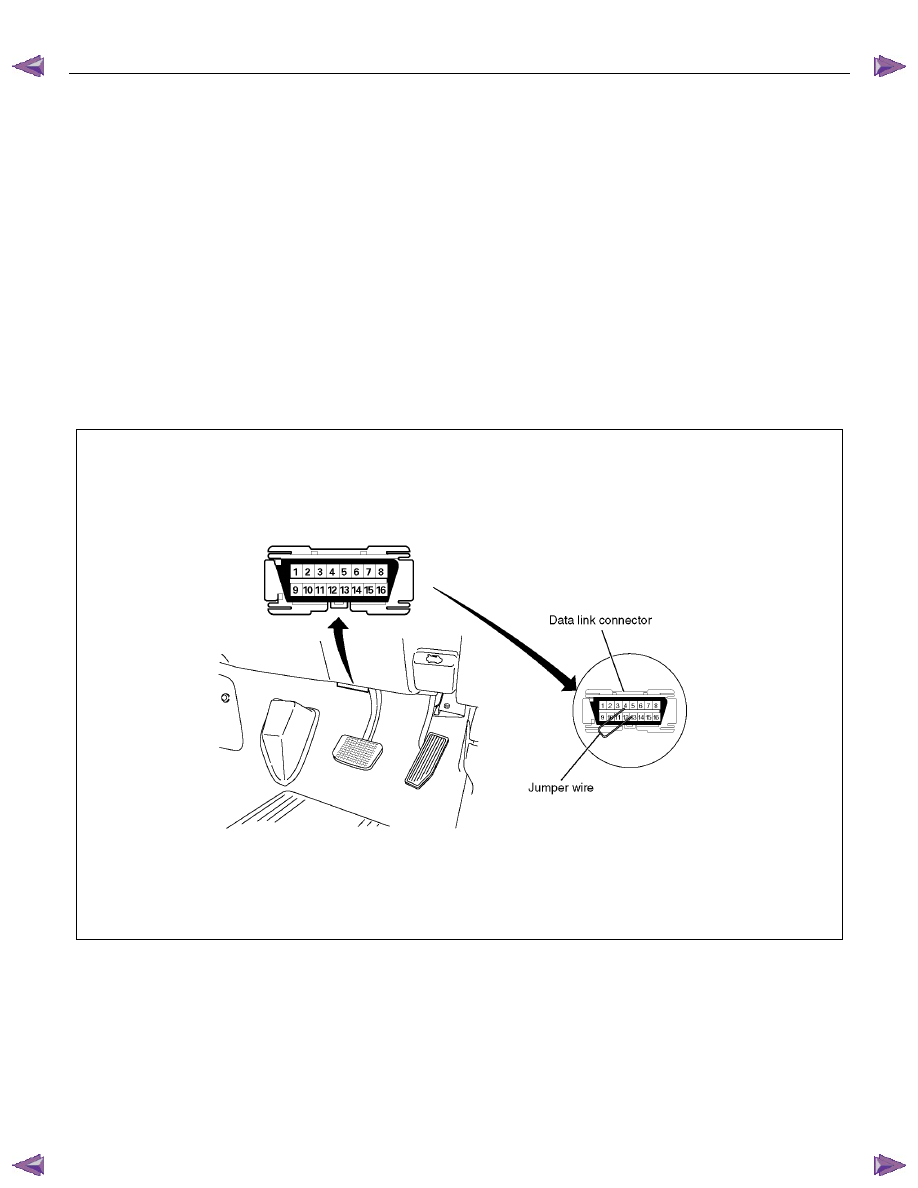
connect it to the DLC and turn the ignition switch “ON”.
Then follow the manufacturer's directions for
communication with the SRS. The scan tool reads
serial data from the SRS control unit’s “Serial Data”
output (terminal 21) to the DLC (terminal 2).
9A1-4 RESTRAINT CONTROL SYSTEM
Basic Knowledge Required
Before using this section of the Service Manual, some
basic knowledge is required. Without this knowledge,
you will have trouble using the diagnostic procedures in
this section. Use care to prevent any harm or unwanted
deployment. Read all cautions in the service manual
and on warning labels attached to SRS components.
Basic Electrical Circuits
You should understand the basic theory of electricity
including series and parallel circuits, and understand
the voltage drops across series resistors. You should
know the meaning of voltage (volts), current (amps),
and resistance (ohms). You should understand what
happens in a circuit with an open or a shorted wire. You
should be able to read and understand a wiring
diagram.
“Flash Code” Diagnostics
Flash code diagnostics can be used to read active
codes and to determine if history codes are present but
cannot be used to clear codes or read history codes.
Flash code diagnostics is enabled by grounding
terminal 4, shorting to terminal 13 of the DLC, with the
ignition switched “ON”. Grounding terminal 4 of the DLC
pulls the “Diagnostics Request” input (Terminal 1) of the
SRS control unit low and signals the SRS control unit to
enter the flash code diagnostic display mode.
060R300052
RESTRAINT CONTROL SYSTEM 9A1-5
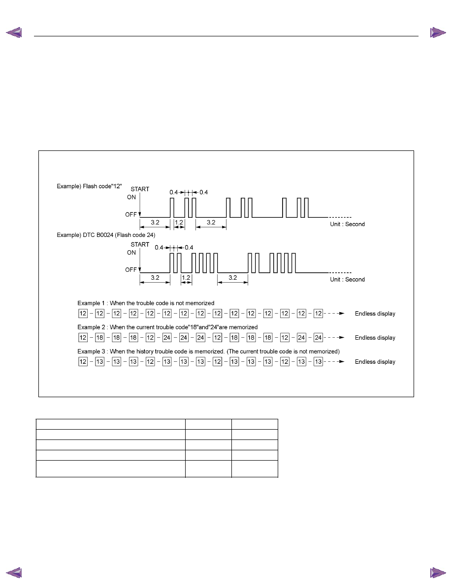
The SRS control unit displays the trouble codes by
flashing the warning lamp. Each code that is displayed
will consist of a number of flashes which represents the
tens digit, a 1.2 second pause, followed by a number of
flashes which represent the ones digit of the code. Each
code is displayed once before moving on to the next
code. After all the codes have been displayed, the
entire code sequence will be continually repeated until
ground is removed from terminal 4 of the DLC.
Two special codes exist when reading in the flash code
mode (Flash Code 12 and Flash Code 13). “Flash
Code 12” will always be the first code displayed when
the flash code mode is enabled. Code 12 is not an
indication of an SRS problem but an indication that the
flash code mode has been enabled. If there are no
active or history codes present, the SRS control unit will
display code 12 until ground is removed from the DLC
at terminal 4. “Flash Code 13” will be displayed if
history codes are present. To read the history codes, a
scan tool must be used.
RTW79AMF000101
DATA LIST (Tech 2)
DISPLAY on Tech 2
UNIT
VALUE
Battery Voltage
V
12.0
Driver Airbag Squib Circuit Resistance
Ohm
1.70-4.33
Passenger Airbag Squib Circuit Resistance
Ohm
1.31-3.08
Driver Seatbelt Status
Buckled/
Not Buckled
Buckled/
Not Buckled
Нет комментариевНе стесняйтесь поделиться с нами вашим ценным мнением.
Текст