Isuzu KB P190. Manual — part 72
POWER-ASSISTED STEERING SYSTEM 3B-27
Supplemental Restraint System Steering Wheel & Column
Service Precaution
This steering wheel and column repair section covers
the Supplemental Restraint System (SRS) steering
column. The following repair procedures are specific to
SRS components. When servicing a vehicle equipped
with Supplemental Restraint System, pay close attention
to all WARNINGS and CAUTIONS.
For detailed explanation about SRS, refer to Restraints
section.
WARNING: THIS VEHICLE HAS A SUPPLEMENTAL
RESTRAINT SYSTEM (SRS). REFER TO THE SRS
COMPONENT AND WIRING LOCATION VIEW IN
ORDER TO DETERMINE WHETHER YOU ARE
PERFORMING SERVICE ON OR NEAR THE SRS
COMPONENTS OR THE SRS WIRING. WHEN YOU
ARE PERFORMING SERVICE ON OR NEAR THE
SRS COMPONENTS OR THE SRS WIRING, REFER
TO THE SRS SERVICE INFORMATION. FAILURE TO
FOLLOW WARNINGS COULD RESULT IN POSSIBLE
AIR BAG DEPLOYMENT, PERSONAL INJURY, OR
OTHERWISE UNNECESSARY SRS SYSTEM
REPAIRS.
SAFE HANDLING OF INFLATOR MODULES
REQUIRES THE PROCEDURES DESCRIBED
BELOW TO BE FOLLOWED FOR BOTH LIVE AND
DEPLOYED MODULES.
SAFETY PRECAUTIONS MUST BE FOLLOWED
WHEN HANDLING A DEPLOYED AIR BAG
ASSEMBLY (AIR BAG). AFTER DEPLOYMENT, THE
AIR BAG ASSEMBLY (AIR BAG) SURFACE MAY
CONTAIN A SMALL AMOUNT OF SODIUM
HYDROXIDE, A BY-PRODUCT OF THE
DEPLOYMENT REACTION, THAT IS IRRITATING TO
THE SKIN AND EYES. MOST OF THE POWDER ON
THE AIR BAG ASSEMBLY (AIR BAG) IS HARMLESS.
AS A PRECAUTION, WEAR GLOVES AND SAFETY
GLASSES WHEN HANDLING A DEPLOYED AIR BAG
ASSEMBLY, AND WASH YOUR HANDS WITH MILD
SOAP AND WATER AFTERWARDS.
WHEN CARRYING A LIVE AIR BAG ASSEMBLY,
MAKE SURE THE BAG AND TRIM COVER ARE
POINTED AWAY FROM YOU. NEVER CARRY AN AIR
BAG ASSEMBLY BY THE WIRES OR CONNECTOR
ON THE UNDERSIDE OF MODULE. IN THE CASE OF
AN ACCIDENTAL DEPLOYMENT, THE BAG WILL
THEN DEPLOY WITH MINIMAL CHANCE OF INJURY.
WHEN PLACING A LIVE AIR BAG ASSEMBLY ON A
BENCH OR OTHER SURFACE, ALWAYS FACE THE
BAG AND TRIM COVER UP, AWAY FROM THE
SURFACE.
NEVER REST A STEERING COLUMN ASSEMBLY
ON THE STEERING WHEEL WITH THE AIR BAG
ASSEMBLY FACE DOWN AND COLUMN VERTICAL.
THIS IS NECESSARY SO THAT A FREE SPACE IS
PROVIDED TO ALLOW THE AIR BAG ASSEMBLY
TO EXPAND IN THE UNLIKELY EVENT OF
ACCIDENTAL DEPLOYMENT. OTHERWISE,
PERSONAL INJURY COULD RESULT.
TO AVOID DEPLOYMENT WHEN
TROUBLESHOOTING THE SRS SYSTEM, DO NOT
USE ELECTRICAL TEST EQUIPMENT, SUCH AS A
BATTERY-POWERED OR A/C-POWERED VOLT-
METER, OHMMETER, ETC., OR ANY TYPE OF
ELECTRICAL EQUIPMENT OTHER THAN SPECIFIED
IN THIS MANUAL. DO NOT USE A NON-POWERED
PROBE-TYPE TESTER.
INSTRUCTIONS IN THIS MANUAL MUST BE
FOLLOWED CAREFULLY, OTHERWISE PERSONAL
INJURY MAY RESULT.
SRS Connectors
CAUTION: The special yellow color connectors are
used for the supplemental restraint system-air bag
circuit.
When removing the cable harness, do not pull the
cables. Otherwise, cable disconnection may occur.
When connecting the SRS connector, insert the
connector completely. Imperfect locking may cause
malfunction of the SRS circuit.
3B-28 POWER-ASSISTED STEERING SYSTEM
Inflator Module
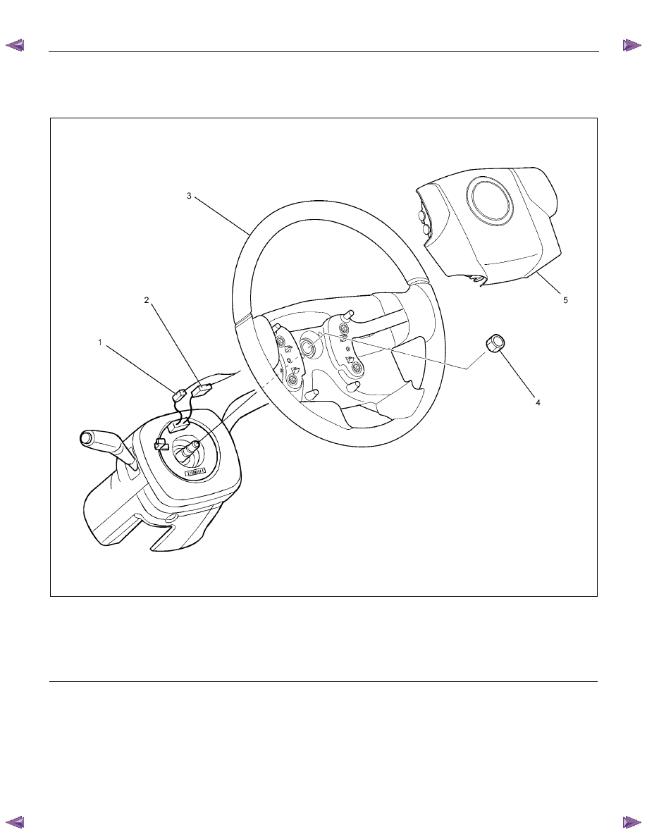
Inflator Module and Associated Parts
RTW73BLF000101
Legend
(1) Horn Lead
(2) SRS Connector
(3) Steering Wheel
(4) Steering Wheel Fixing Nut
(5) Inflator Module or Horn Pad

POWER-ASSISTED STEERING SYSTEM 3B-29
Removal
1. Turn the steering wheel so that the vehicle's wheels
are pointing straight ahead.
2. Turn the ignition switch to "LOCK".
3. Disconnect the battery "-" terminal cable, and wait at
least 5 minutes (with SRS air bag).
4. Disconnect the yellow 2-way SRS connector located
under the steering column (with SRS air bag).
CAUTION: The wheels of the vehicle must be
straight ahead and the steering column in the
"LOCK" position before disconnecting the steering
wheel. Failure to do so will cause the coil assembly
to lose its centering which will cause damage to the
coil assembly (with SRS air bag).
5. Disable the SRS (Refer to "Disabling the SRS" in
this section) (with SRS air bag).
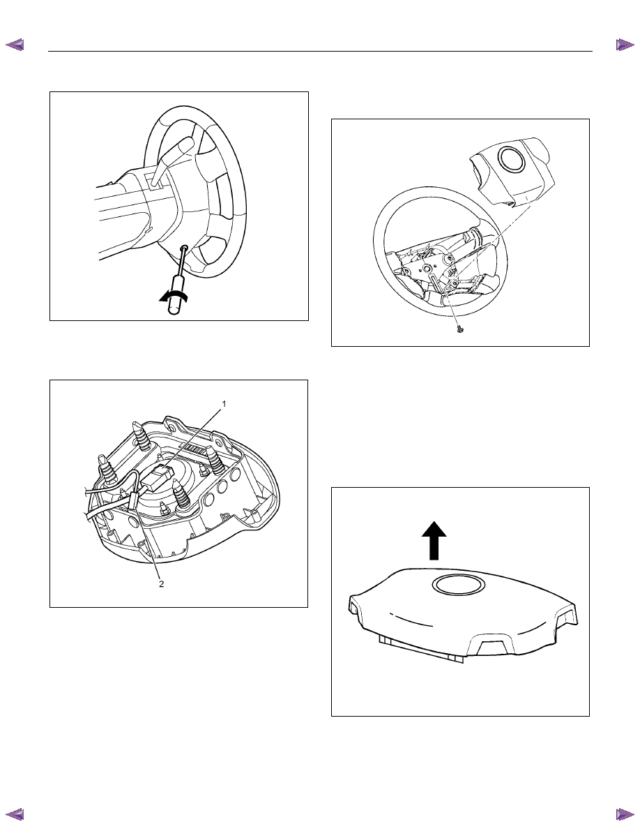
6. Check the holes on both sides of the steering cover
(with SRS air bag).
060R300025
7. Check the position of the pins in their holes. Push
the pin in the direction of the arrow (with SRS air
bag).
RTW73BSH000101
8. Push the four pins with a φ 5~6 mm (0.20~0.24 in)
bar (with SRS air bag).
060R300031
9. Cancel the lock to release the four pins (with SRS
air bag).
3B-30 POWER-ASSISTED STEERING SYSTEM
10. Loosen the horn pad fixing screw at the rear of the
steering wheel (without SRS air bag).
430R300009
11. Disconnect the SRS air bag connector (1) and horn
lead connector (2) located behind the air bag
assembly and remove the air bag assembly (with
SRS air bag).
RTW73BSH001101
12. Remove the horn pad and the horn leads at the
center of the wheel (without SRS air bag).
NOTE: It should be removed first from the bottom
spokes.
RTW73BSH000601
WARNING: THE INFLATOR MODULE SHOULD
ALWAYS BE CARRIED WITH THE COVER AWAY
FROM YOUR BODY AND SHOULD ALWAYS BE
LAID ON A FLAT SURFACE WITH THE COVER SIDE
UP. THIS IS NECESSARY BECAUSE A FREE SPACE
IS PROVIDED TO ALLOW THE AIR CUSHION TO
EXPAND IN THE UNLIKELY EVENT OF
ACCIDENTAL DEPLOYMENT. OTHERWISE,
PERSONAL INJURY MAY RESULT (with SRS air
bag).
430R300007
Нет комментариевНе стесняйтесь поделиться с нами вашим ценным мнением.
Текст