Isuzu KB P190. Manual — part 71

POWER-ASSISTED STEERING SYSTEM 3B-23
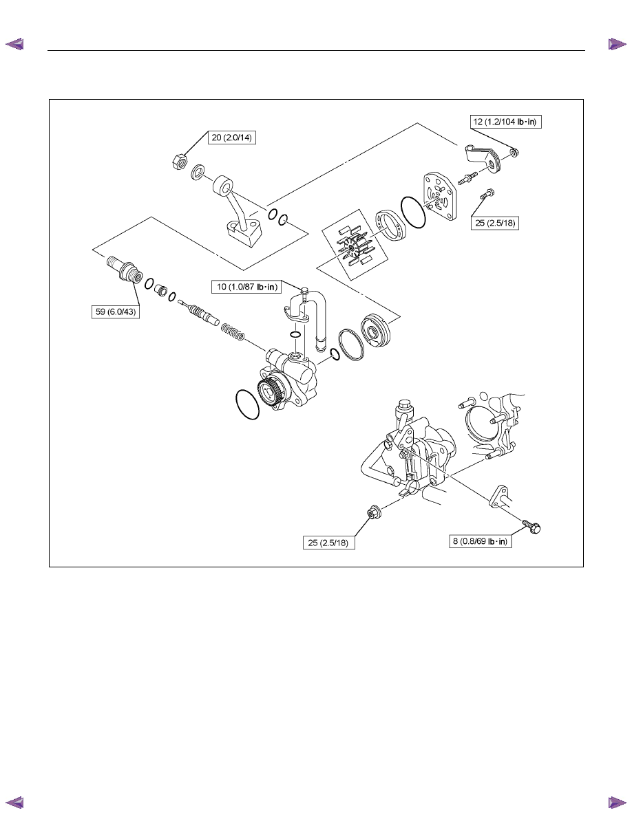
Power Steering Pump Disassembled View
RTW53BLF002001
Legend
(1) Bolt
(2) Suction Pipe
(3) O-ring
(4) O-ring
(5) O-ring
(6) O-ring
(7) Side Plate
(8) Rotor and Vanes
(9) Pump Cartridge Assembly
(10) O-ring
(11) Rear Housing
(12) Bolt
(13) Spring
(14) Relief
Valve
(15) O-ring
(16) Connector
(17) O-ring
(18) Joint
(19) Washer
(20) Nut
(21) Bracket
(22) Nut
(23) Shaft and Housing Assembly
3B-24 POWER-ASSISTED STEERING SYSTEM
Disassembly
1. Clean the oil pump with solvent (plug the discharge
and suction ports to prevent the entry of solvent).
Be careful not to expose the oil seal of the shaft
assembly to solvent.
2. Remove the bolt, suction pipe and O-ring.
3. Remove the nut and bracket.
4. Remove the nut, washer and joint.
5. Remove the connector, O-ring, relief valve and
spring.
6. Remove the bolt, rear housing and O-ring.
7. Remove the pump cartridge assembly and the side
plate from the shaft. Remove two O-rings.
Inspection and Repair
Make all necessary adjustments, repairs, and part
replacements if wear, damage, or other problems are
discovered during inspection.
Rotor
442RS002
Check that the groove in the vane is free from excessive
wear and that the vane slides smoothly. When part
replacement becomes necessary, the pump cartridge
should be replaced as a subassembly.
Vane
442RS003
Sliding faces of the vane should be free from wear. (In
particular the curved face at the tip that makes contact
with the cam should be free from wear and distortion).
When part replacement becomes necessary, the pump
cartridge should be replaced as a subassembly.
Cam
The inner face of the cam should have a uniform
contact pattern without a sign of step wear. When part
replacement becomes necessary, the pump cartridge
should be replaced as a subassembly.
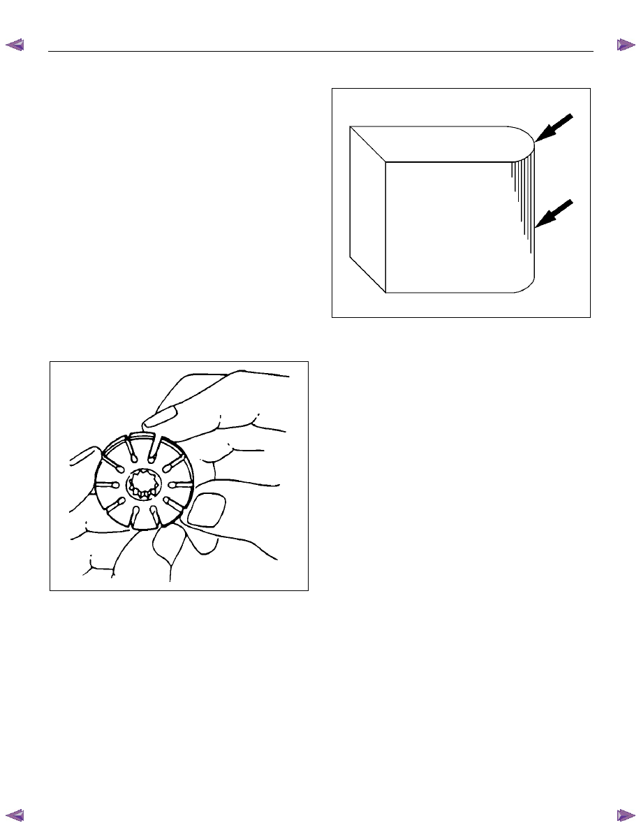
Side Plate
The sliding faces of parts must be free from step wear
(more than 0.01 mm (0.0004 in)), which can be felt by a
finger nail.
Parts with minor scores may be reused after lapping the
face.
Relief Valve
The sliding face of the valve must be free from burrs
and damage. Parts with minor scores may be reused
after smoothing with emery cloth (#800 or finer).
Shaft and Housing Assembly
The bushing fitting face on the shaft must be free from
damage and wear.
O-ring
Be sure to discard used parts, and always use new
parts for installation. Prior to installation, lubricate all
seals and rings with power steering fluid.
POWER-ASSISTED STEERING SYSTEM 3B-25
Reassembly
1. Install two new O-rings on shaft and housing
assembly. Be sure to discard used O-ring.
2. Install side plate.
CAUTION: When installing side plate, be careful not
to damage its inner surface. A damaged side plate
may cause poor pump performance, pump seizure
or oil leakage.
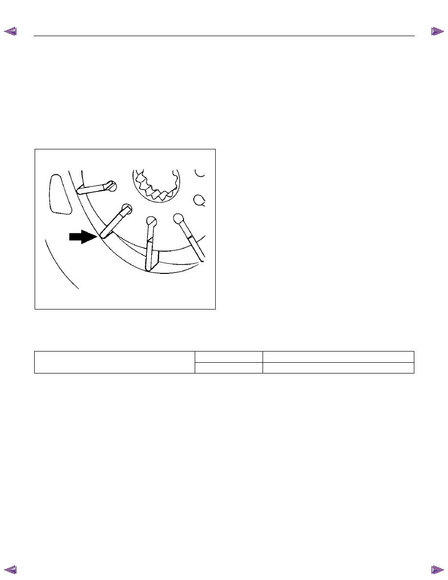
3. Install the vanes on rotor with curved face in contact
with the inner wall of cam.
442RS005
4. Install rotor and vanes on cam.
5. Install pump cartridge assembly on shaft and
housing assembly.
6. Install a new O-ring on rear housing. Be sure to
discard used O-ring. Then install bolt and tighten it to
specified torque.
Torque: 25 N
⋅⋅⋅⋅m (2.5 kgf⋅⋅⋅⋅m/18 lb⋅⋅⋅⋅ft)
7. Install a new O-ring on suction pipe. Be sure to
discard used O-ring. Then install bolt and tighten it to
specified torque.
Torque: 10 N
⋅⋅⋅⋅m (1.0 kgf⋅⋅⋅⋅m/87 lb⋅⋅⋅⋅in)
8. Install relief valve and spring.
9. Install a new O-ring on connector. Be sure to discard
used O-ring. Tighten the connector to specified
torque.
Torque: 59 N
⋅⋅⋅⋅m (6.0 kgf⋅⋅⋅⋅m/43 lb⋅⋅⋅⋅ft)
10. Install new O-rings on joint. Be sure to discard used
O-rings. Temporarily tighten the nut with washer.
11.
Install bracket. Then install nut and tighten it to
specified torque.
Torque: 12 N
⋅⋅⋅⋅m (1.2 kgf⋅⋅⋅⋅m/104 lb⋅⋅⋅⋅in)
12. Tighten the nut to the specified torque (This nut was
temporarily tightened in step 10).
Torque: 20 N
⋅⋅⋅⋅m (2.0 kgf⋅⋅⋅⋅m/14 lb⋅⋅⋅⋅ft)
Main Data and Specifications
General Specifications
Oil pump
Type
Vane
Operating
fluid
ATF DEXRON
®
―III
3B-26 POWER-ASSISTED STEERING SYSTEM
Torque Specifications
N
⋅m (kgf⋅m/Ib⋅ft)
RTW73BLF000701
Нет комментариевНе стесняйтесь поделиться с нами вашим ценным мнением.
Текст