Isuzu KB P190. Manual — part 496
ENGINE CONTROL SYSTEM (4JK1/4JJ1) 6E-367
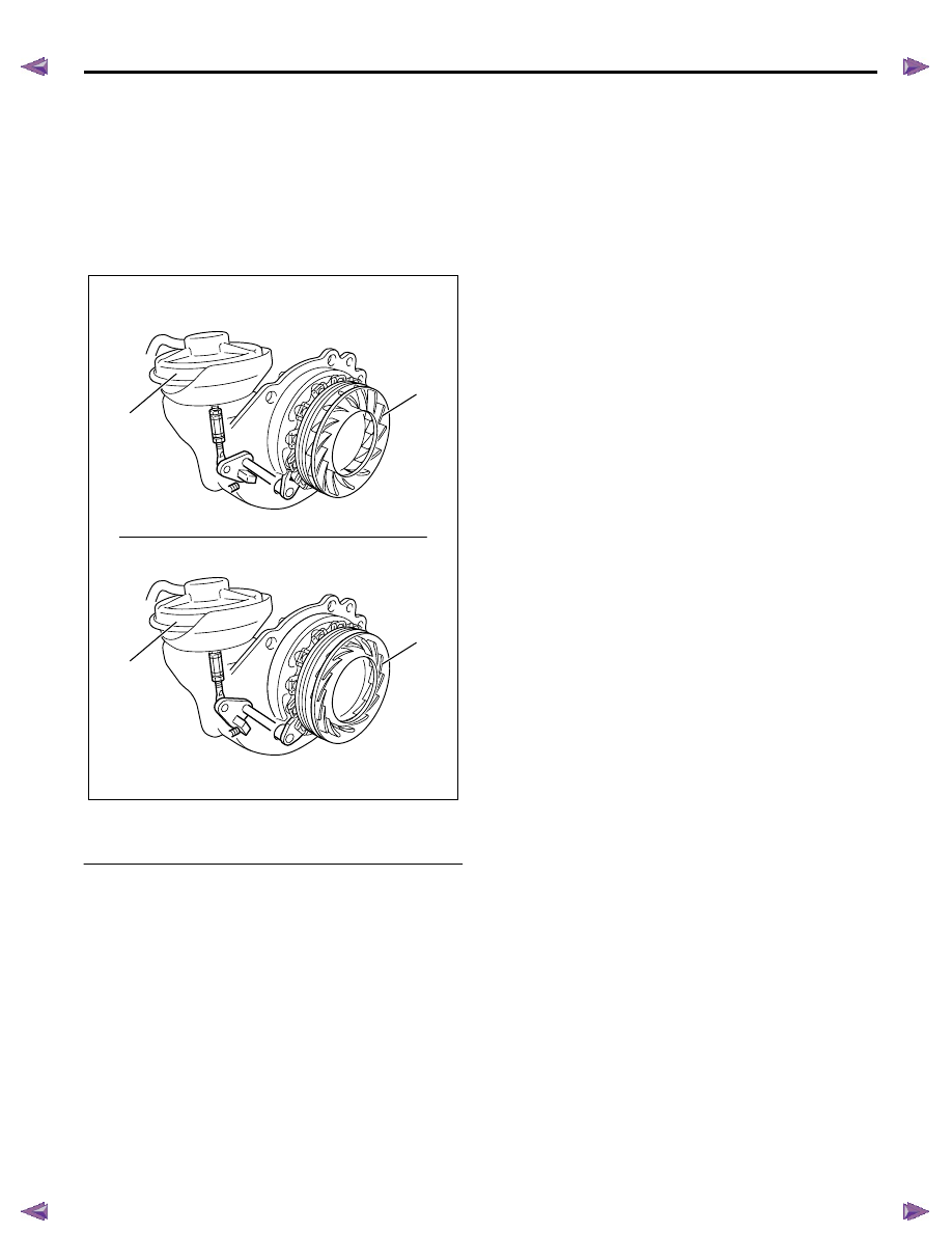
The amount of air pressure rise and air volume
delivered to the engine from the compressor outlet is
regulated by a waste gate valve in the exhaust housing.
The position of the waste gate valve is controlled by the
amount of pressure built up on the intake side of the
turbocharger. The diaphragm on the inside of the waste
gate is pressure sensitive, and controls the position of
the valve inside the turbocharger. The position of the
valve will increase or decrease the amount of boost to
the turbocharger. (Standard output engine)
Legend
1. Turbocharger nozzle control actuator
2. Nozzle
The amount of air pressure rise and air volume
delivered to the engine from compressor outlet is
regulated by a turbocharger nozzle control actuator
indirectly. The position of the turbocharger nozzle is
controlled by the ECM. The ECM utilizes a
turbocharger nozzle control solenoid valve and a boost
pressure sensor to control the turbocharger nozzles.
When the engine is not under load, the turbocharger
nozzles are in an open position (A), or no boost
condition (vacuum pressure supply to the actuator is
reduced). When the engine is under load, the ECM
commands the control solenoid valve to close the
turbocharger nozzles (B), thus increasing the boost
(vacuum pressure supply to the actuator is increased).
The ECM will vary the boost dependant upon the load
requirements of the engine. The ECM uses a pulse
width modulation (PWM) on the control circuit to open
and control the solenoid valve. (High output engine)
The charge air cooler also helps the performance of the
diesel. Intake air is drawn through the air cleaner and
into the turbocharger compressor housing. Pressurized
air from the turbocharger then flows forward through
the charge air cooler located in the front of the radiator.
From the charge air cooler, the air flows back into the
intake manifold.
The charge air cooler is a heat exchanger that uses air
flow to dissipate hear from the intake air. As the
turbocharger increases air pressure, the air
temperature increases. Lowering the intake air
temperature increases the engine efficiency and power
by packing more air molecules into the same space.
RTW76EMH000201
A
B
1
2
1
2
6E-368 ENGINE CONTROL SYSTEM (4JK1/4JJ1)
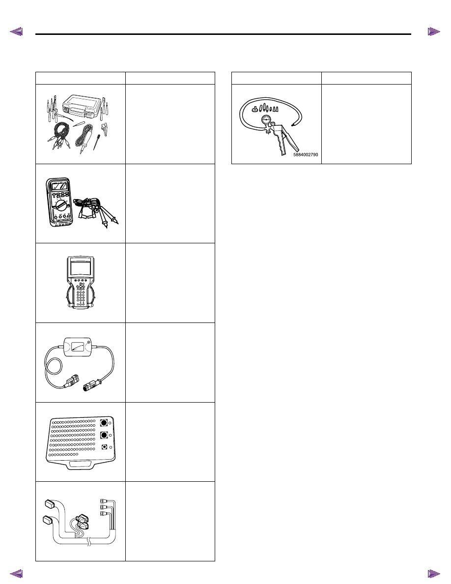
Special Tools and Equipment
Special Tools and Equipment
Illustration
Tool Number/ Description
5-8840-2835-0 (J-35616-C)
Connector Test Adapter Kit
(With Test Lamp)
5-8840-0285-0 (J-39200)
Digital Multimeter
Tech2 Kit
CAN-di Module
Breaker Box
Adapter Harness
5884028350
5884002850
AAW0Z0SH015701
1851110030
A
B
C
A
B
C
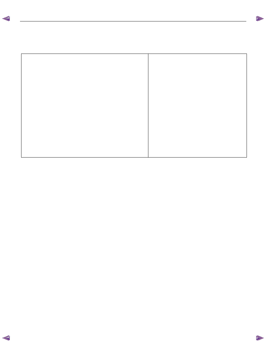
5-8840-0279-0 (J-23738-A)
Vacuum Pump
Illustration
Tool Number/ Description
EXHAUST SYSTEM (4JK1/4JJ1) 6F-1
SECTION 6F
EXHAUST SYSTEM
CONTENTS
Exhaust Silencer and Exhaust Pipe . . . . ... 6F-2
Main Data and Specifications. . . . . . .. 6F-2
Components. . . . . . . . . . . . . 6F-3
Removal . . . . . . . . . . . . . . .. 6F-4
Installation . . . . . . . . . . . . . ... 6F-4
Inspection and Repair . . . . . . . . . . 6F-5
Torque Specifications. . . . . . . . . .. 6F-6
EGR Cooler . . . . . . . . . . . . . . 6F-7
Components (Standard Output) . . . . . .. 6F-7
Components (High Output) . . . . . . . . 6F-8
Removal . . . . . . . . . . . . . . .. 6F-9
Installation (Standard Output) . . . . . . . 6F-9
Installation (High Output). . . . . . . . . 6F-10
6F-2 EXHAUST SYSTEM (4JK1/4JJ1)
Exhaust Silencer and Exhaust Pipe
Main Data and Specifications
Front pipe
Pipe outside diameter
× thickness
mm (in)
50.8
× 1.5 (2.0 × 0.059) and
60.5
× 1.5 (2.38 × 0.059)
Middle pipe
Pipe outside diameter
× thickness
mm (in)
60.5
× 1.5 (2.38 × 0.059)
Silencer & tail pipe
Type
Circular section-shell construction of double skin
and end plates, internal construction of baffles
and perforated tubes.
Tail pipe outside diameter
× thickness
mm (in)
Standard output: 60.5
× 1.6 (2.38 × 0.063)
High output:
63.5
× 1.6 (2.5 × 0.063)
Length
mm (in)
Approximately 1335 (52.6)
Mounting
Number of suspension points
4
Type
Rubber
Нет комментариевНе стесняйтесь поделиться с нами вашим ценным мнением.
Текст