Isuzu KB P190. Manual — part 215
ENGINE MECHANICAL 6A – 55
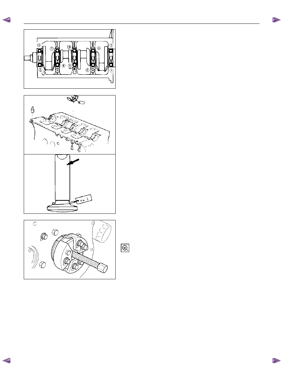
2. Loosen the crankshaft bearing cap bolts in numerical
order a little at a time.
If the crankshaft bearings are to be reinstalled, mark
their fitting positions by tagging each bearing with the
cylinder number from which it was removed.
29. Crankshaft Thrust Bearing
30.Crankshaft
31. Crankshaft Upper Bearing
If the crankshaft upper bearings are to be reinstalled, mark
their fitting positions by tagging each bearing with the
cylinder number from which it was removed.
32. Tappet
If the tappets are to be reinstalled, mark their fitting
positions by tagging each tappet with the cylinder number
from which it was removed.
33. Crankshaft Rear Oil Seal
• With the oil seal pushed in deep, install the special
tool as shown in the illustration and remove the oil
seal.
Oil Seal Remover: 5-8840-2360-0
34. Cylinder Body
015RY00003
015RY00004
015RY00005
015LV002
6A – 56 ENGINE MECHANICAL
MINOR COMPONENTS
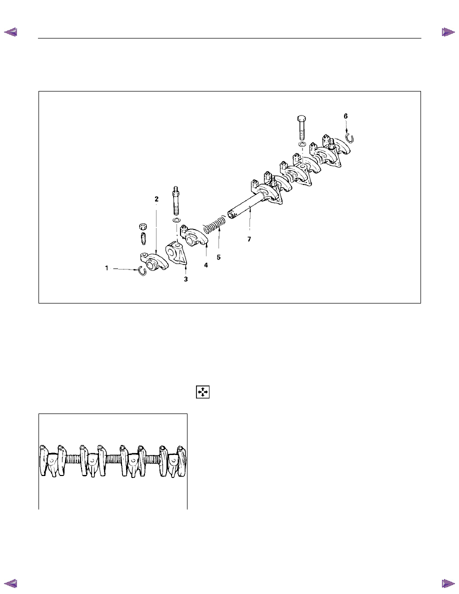
ROCKER ARM SHAFT AND ROCKER ARM
Disassembly Steps
1.
Rocker arm shaft snap ring
5.
Rocker arm shaft spring
2.
Rocker arm
6.
Rocker arm shaft snap ring
3.
Rocker arm shaft bracket
7.
Rocker arm shaft
4.
Rocker
arm
Disassembly
1. Rocker Arm Shaft Snap Ring
2. Rocker
Arm
3. Rocker Arm Shaft Bracket
1. Use a pair of pliers to remove the snap rings.
2. Remove the rocker arms.
3. Remove the rocker arm shaft brackets.
If the rocker arms and rocker arm shaft brackets are to
be reinstalled, mark their installation positions by
tagging each rocker arm and rocker arm shaft bracket
with the cylinder number from which it was removed.
4. Rocker
Arm
5. Rocker Arm Shaft Spring
6. Rocker Arm Shaft Snap Ring
7. Rocker Arm Shaft
011RY00009
011RY00010
ENGINE MECHANICAL 6A – 57
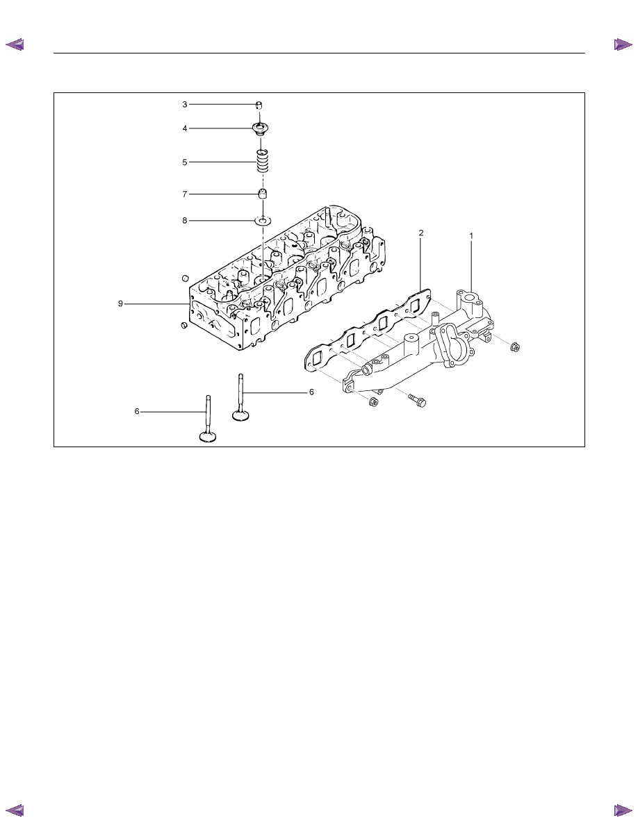
CYLINDER HEAD
RTW46ALF001201
Disassembly Steps
1.
Intake manifold
6.
Intake and exhaust valve
2.
Intake manifold gasket
7.
Valve stem oil seal
3.
Split collar
8.
Valve spring lower seat
4.
Valve spring upper seat
9.
Cylinder head
5.
Valve spring
6A – 58 ENGINE MECHANICAL
Disassembly
1. Intake
Manifold
2. Intake Manifold Gasket
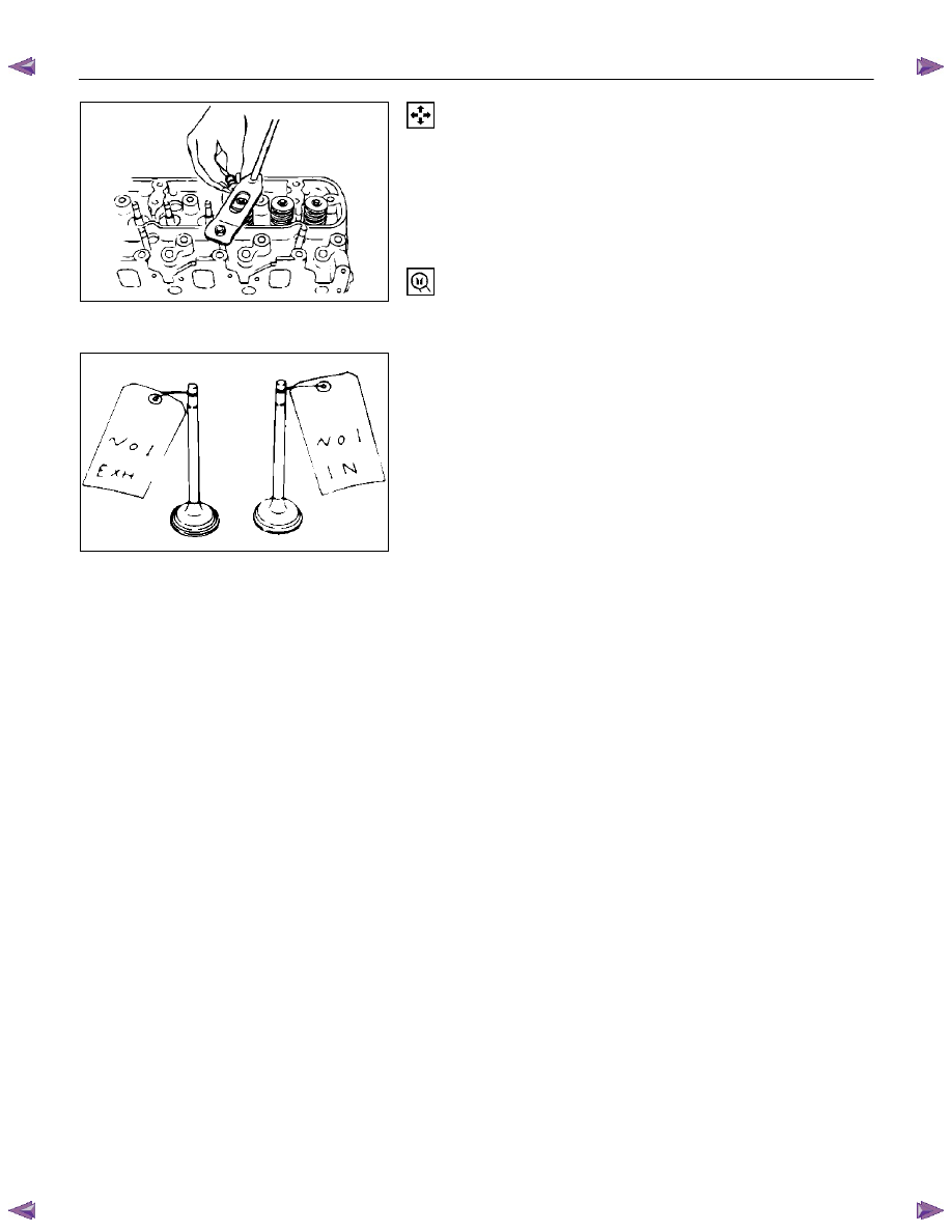
3. Split
Collar
1. Place the cylinder head on a flat wooden surface.
2. Use the spring compressor to remove the split collars.
Do not allow the valve to fall from the cylinder head.
Spring Compressor: 9-8523-1423-0
4. Valve Spring Upper Seat
5. Valve
Spring
6. Intake and Exhaust Valve
If the intake and exhaust valves are to be reinstalled, mark
their installation positions by tagging each valve with the
cylinder number from which it was removed.
If the intake and exhaust valves are to be replaced, the
valve guides must also be replaced.
7. Valve Stem Oil Seal
8. Valve Spring Lower Seat
9. Cylinder
Head
011RY00011
011LX022
Нет комментариевНе стесняйтесь поделиться с нами вашим ценным мнением.
Текст