Isuzu KB P190. Manual — part 396
FUEL SYSTEM (4JK1/4JJ1) 6C-43
Removal
Note: When repairs to the fuel system have been
completed, start the engine and check the fuel system
for loose connections or leakage. For the fuel system
diagnosis, see Section "Drivability and Emission".
1. Remove the fuel tank assembly (8). Refer to "Fuel
Tank Removal" in this section.
2. Disconnect the quick connector (1) of the fuel tube
from the fuel gauge unit.
140R100035
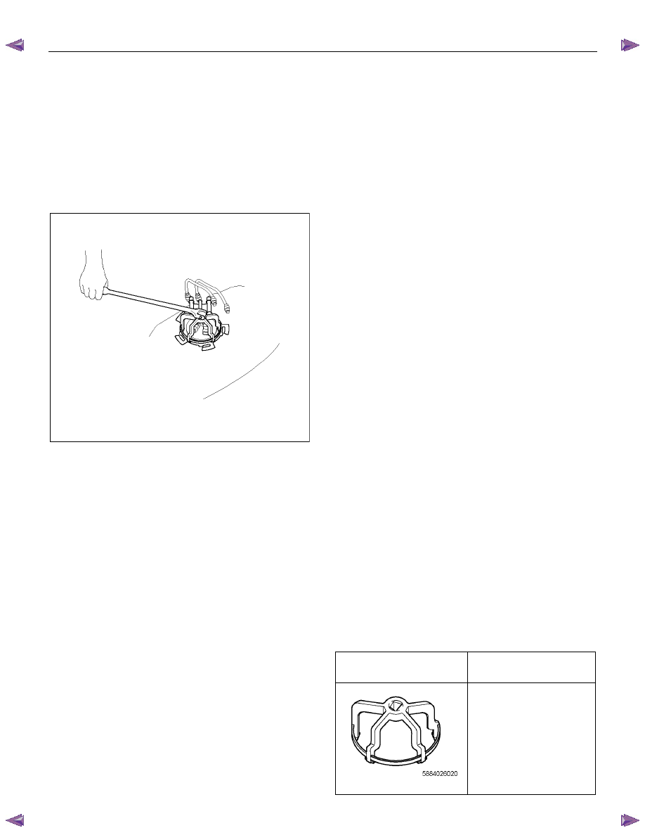
3. Remove the retainer ring (3) from the fuel tank
with the removal tool 5-8840-2602-0.
4. Slowly remove the fuel gauge unit (6) from the fuel
tank as no bend float arm.
Note: Cover opening for the fuel gauge unit on the fuel
tank to prevent any dust entering.
5. Discard the fuel gauge unit seal (7) because it
cannot be reused.
Installation
1. Clean the seal surface of the fuel tank and the fuel
gauge unit.
Note: If there is dust on the seal surface, it can cause a
fuel leak.
2. Install the new fuel gauge unit seal (7) to the
opening of the fuel tank along the groove.
3. Slowly install the fuel gauge unit (6) into the fuel
tank so there is no bend in the float arm.
4. Set the flange of the fuel gauge unit on the fuel
gauge unit seal as mating convexity of the fuel
gauge unit and reentrant of the fuel tank.
5. Slowly lock the retainer ring (3) to the fuel tank with
the remover tool 5-8840-2602-0.
6. Connect the quick connector (1) of the fuel tube to
the gauge unit.
Note: Pull off the left checker of the fuel pipe.
Note: Refer to "Fuel Tube/Quick Connector Fittings" in
this section when performing any repairs.
7. Check for leak.
Method of leak check.
1. Plug the end of the quick connector and
breather hose (Pull off the breather hose from
fuel tank) and tighten fuel filler cap until at least
one click is heard.
2. Apply soapy water around the fuel gauge unit
seal area.
3 Pressure air into the fuel tank from the end of
the breather pipe at 34.3 kPa (0.35 kg / cm
2
/ 5
psi) over 15 seconds.
4 Verify that no bubbles from around the fuel
gauge unit seal area.
8. Install the fuel tank assembly (8).
Note: Refer to "Install the fuel tank" in this section.
Special Tool
ILLUSTRATION
PART NO.
PART NAME
5-8840-2602-0
Remover: fuel pump
retainer ring
6C-44 FUEL SYSTEM (4JK1/4JJ1)
Fuel Tube / Quick - Connector Fittings
Precautions
• Do not light a match or create a flame.
• Keep flames away from your work area to prevent
flammable materials from catching fire.
• Disconnect the battery ground cable to prevent
electrical shorts.
• Pre−treat the piping system or associated parts
from thermal damage or from spattering when
welding or similar heat
−generating work.
Cautions During Work
Do not expose the assembly to battery electrolyte or do
not wipe the assembly with a cloth used to wipe off spilt
battery electrolyte.
Piping that has been splattered with battery electrolyte
or battery electrolyte soaked cloth that was wiped on the
piping cannot be used.
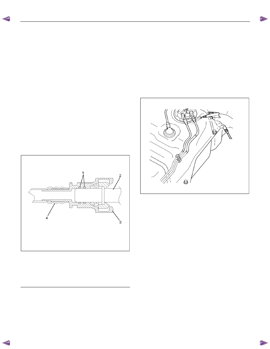
140R100032
Legend
1. O-ring
2. Port
3. Connector
4. Plastic
Tube
Removal
1. Open the fuel cap to relieve the fuel pressure in
the tank. Use compressed air to remove any dirt
on the fuel quick connect fittings prior to
disconnecting the fittings. When disconnecting the
fuel pipe, cover the area with a cloth to prevent
fuel from splashing as the fuel pipe may still have
some pressure in it.
140R100002
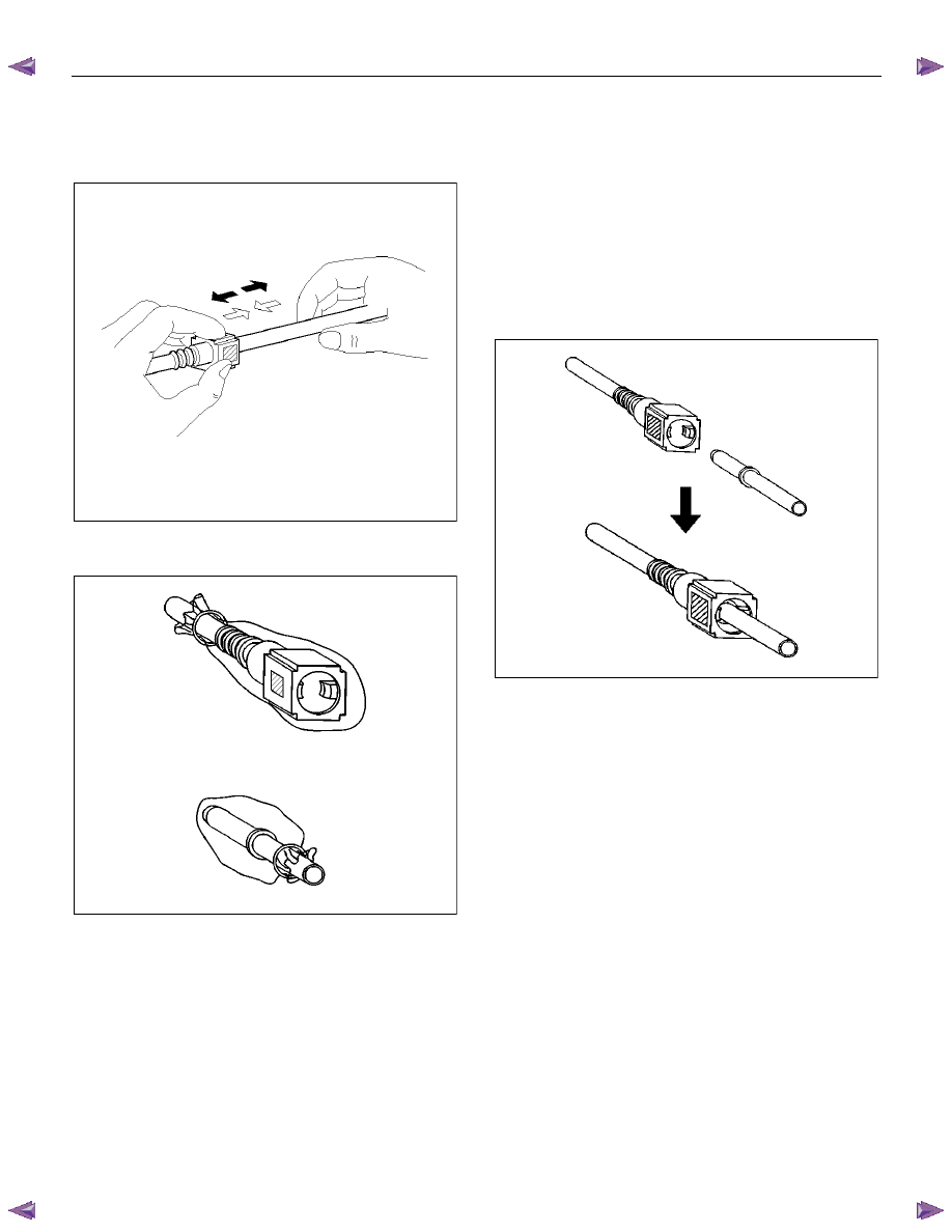
2. For removal of the quick connector, hold the quick
connector in one hand, and pull out the connector
with the other hand while pressing the square
release button of the connector, as illustrated.
FUEL SYSTEM (4JK1/4JJ1) 6C-45
Note: Do not use tools of any kind. Only use bare hands
when disconnecting the connector. Use a lubricant (light
oil) and/or push and pull the connector until the pipe is
disconnected.
140R100037
Cover the connectors that were removed with a plastic
bag, to prevent dust or rain water from entering.
140R100028
Reuse of Quick-Connector
• Replace the port and connector if a scratch, dent
or crack is found.
• Remove any dirt build up on the port when
installing the connector. Replace the connector, if
there is any rust, dents or scratches.
• After cleaning the port, insert it straight into the
connector until it clicks. After it clicks, try pulling it
out at 49 N (5 kg / 11 lb) to make sure that it is not
drawn and is securely locked.
140R100036
Assembling Advice
By applying engine oil or light oil to the pipe, port makes
pipe assembly easier. The pipe assembly should take
place immediately after applying oil (to prevent dust
from sticking to the pipe surface - which may decrease
sealing ability).
Test/Inspection After Assembling
1. Reconnect the battery negative cable.
2. Start the engine and observe the engine idle
speed. The presence of dirt in the fuel system may
affect the fuel injection system.
3. Check for fuel leakage from the connector.
6C-46 FUEL SYSTEM (4JK1/4JJ1)
Filler Neck
Removal
1. Remove the fuel tank.
Note: Refer to "Fuel Tank" in this section.
2. Put a marking on the following points as the filler
neck assembly is restored.
• Each joint area of the hose (to restore axial
direction and insertion length of the hose)
• Each fasten area of the clamp (to restore axial
direction and position of the clamp)
• Each bolt in the clamp (to restore fasten length
of bolt in the clamp)
• The band clip (to restore position and fasten
length of the band clip)
Note: Cover end of each hose and pipe to prevent any
dust entering.
Installation
1. Align each marking and restore the following point.
• Each joint area of the hose (Restore axial
direction and insertion length of the hose)
• Each fasten area of the clamp (Restore axial
direction and position of the clamp)
Tightening torque: 2.5 N·m (0.25 kg
⋅⋅⋅⋅m /21.7 lb in)
Filler neck side except flat deck model.
• Each bolt in the clamp (Restore fasten length of
bolt in the clamp)
Tightening torque: 2.5 N·m (0.25 kg
⋅⋅⋅⋅m /21.7 lb in)
Filler neck side except flat deck model.
• The band clip (Restore position and fasten
length of the band clip)
2. Install the fuel tank.
Note: Refer to "Fuel Tank" in this section.
Нет комментариевНе стесняйтесь поделиться с нами вашим ценным мнением.
Текст