Isuzu KB P190. Manual — part 395

FUEL SYSTEM (4JK1/4JJ1) 6C-39
Fuel Sedimenter Switch
Inspection
1. Check that there is continuity between the switch
connector terminals when the float in the fuel
sedimenter is above the water drain line.
2. Turn on the ignition switch, remove the fuel
sedimenter connector, and connect the terminals
of the connectors on the harness side. Confirm
that the sedimenter warning lamp lights up.
If abnormalities are detected during the check, replace
the switch parts and carry out repairs in case of
defective connection between circuits or short circuits.
RTW76CSH001101
Legend
1. Sensor
2. Connector on The Vehicle Side
3. Harness
4. Drain
Valve
6C-40 FUEL SYSTEM (4JK1/4JJ1)
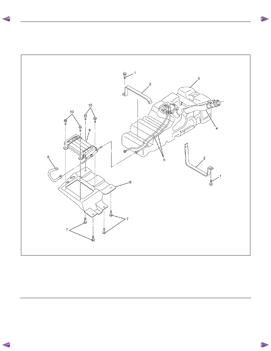
Fuel Tank and Fuel Cooler
Fuel Tank and Associated Parts
RTW76CLF000501
Legend
1. Bolt; Fuel Tank
2. Fuel Tank Band
3. Fuel
Tank
4. Fuel Filler Hose and Pipe
5. Fuel Tube/Quick Connector
6. Bracket; Fuel Cooler
7. Bolt; Fuel Cooler Bracket
8. Fuel Return Hose
9. Fuel
Cooler
10. Bolt; Fuel Cooler
FUEL SYSTEM (4JK1/4JJ1) 6C-41
Removal
Note: When repairs to the fuel system have been
completed, start the engine and check the fuel system
for loose connections or leakage. For the fuel system
diagnosis, see Section "Drivability and Emission".
1. Disconnect the battery ground cable.
2. Slowly loosen the fuel filler cap.
Note: Be careful that fuel does not spout out because of
change of pressure in the fuel tank.
Note: Cover opening of the filler neck to prevent any
dust entering.
3. Jack up the vehicle.
4. Disconnect the quick connector (5) of the fuel tube
at the fuel cooler way.
5. Remove fuel return hose (8) from the pipe.
6. Remove fixing bolt (7) of the bracket fuel cooler
and remove bracket fuel cooler (6).
Note: Cover the opening of the pipe to prevent any dust
and fuel leakage.
Note: For remove fuel cooler, Remove bolts (10) of the
fuel cooler and remove fuel cooler.
7. Support underneath of the fuel tank with a lifter.
8. Remove the inner liner of the wheel house at rear
left side.
9. Remove fixing bolt of the filler neck from the body.
10. Disconnect the quick connector (5) of the fuel tube
from the fuel pipe and the evapo tube from evapo
joint connector.
Note: Cover the quick connector to prevent any dust
entering and prevent fuel leakage.
Note: Refer to "Fuel Tube/Quick Connector Fittings" in
this section when performing any repairs.
11.
Remove fixing bolt (1) of the tank band and
remove the tank band (2).
12. Disconnect the pump and sender connector on the
fuel pump and remove the harness from the weld
clip on the fuel tank.
13. Lower the fuel tank (3).
Note: When lowering the fuel tank from the vehicle, do
not scratch the hoses and tubes by contact with other
parts.
Installation
1. Raise the fuel tank.
Note: When raising the fuel tank to the vehicle, do not
scratch the hoses and tubes by contact with other parts.
2. Connect the pump and sender connector to the
fuel pump and install the harness to the weld clip
on the tank.
Note: The connector must be securely connected
against the stopper.
3. Install the tank band and fasten bolt.
Torque: 68 N
⋅⋅⋅⋅m (6.9 kg⋅⋅⋅⋅m /50 lb ft)
Note: The anchor of the tank band must be securely
installed to the guide hole on the frame.
4. Connect the quick connector of the fuel tube to the
fuel pipe and the evapo tube from evapo joint
connector.
Note: Pull off the left checker on the fuel pipe.
Note: Refer to "Fuel Tube/Quick Connector Fittings" in
this section when performing any repairs.
5. Install the filler neck to the body with bolt.
Note: For install the fuel cooler to the bracket with bolt.
Torque: 6.5 N
⋅⋅⋅⋅m (0.7 kg⋅⋅⋅⋅m /61 lb in)
6. Install the bracket to Frame with bolt.
Torque: 48 N
⋅⋅⋅⋅m (4.9 kg⋅⋅⋅⋅m /35 lb ft)
7. Install the fuel return hose at the fuel cooler way.
8. Install the quick connector at the fuel cooler way.
9. Install the inner liner of the wheel house at rear left
side.
10. Remove lifter from the fuel tank.
11. Lower the vehicle.
12. Tighten the filler cap until at least three clicks.
13. Connect the battery ground cable.

6C-42 FUEL SYSTEM (4JK1/4JJ1)
Fuel Gauge Unit
Fuel Gauge Unit and Associated Parts
RTW56CLF001001
Legend
1. Fuel Tube/Quick Connector
2. Fuel Feed Port
3. Retainer Ring (Fuel Gauge Unit Lock)
4. Connector; Fuel Gauge Unit
5. Fuel Return Port
6. Fuel Gauge Unit and Sender Assembly
7. Seal; Fuel Gauge Unit
8. Fuel Tank Assembly
Нет комментариевНе стесняйтесь поделиться с нами вашим ценным мнением.
Текст