Isuzu KB P190. Manual — part 1430

9A1-38 RESTRAINT CONTROL SYSTEM
DTC Chart Test Description
Number(s) below refer to step number(s) on the
diagnostic chart:
2. This test determines whether the SRS control unit is
malfunctioning.
3. This test isolates the malfunction to one side of the
SRS coil assembly yellow 2–pin connector at the
base of the steering column.
4. This test determines whether the malfunction is in
the “Driver Bag High” circuit.
5. This test determines whether the malfunction is in
the “Driver Bag Low” circuit.
6. This test determines whether the malfunction is in
the SRS coil assembly or the driver air bag
assembly.
Diagnostic Aids
An intermittent condition is likely to be caused by a short
to ground/+B in the driver air bag assembly circuit.
Inspect circuits “Driver Bag High” and “Driver Bag Low”
carefully for cutting or chafing.
DTC B0026 (Flash Code 26) Driver Air Bag Squib Circuit Short to Battery Voltage
Step Action
Yes
No
1
Was the “SRS Diagnostic System Check” performed?
Go to Step 2
Go to the “SRS
Diagnostic System
Check”
2
1. When measurements are requested in this chart use a 5-
8840-0366-0 DMM with a correct terminal adapter from 5-
8840-2835-0.
2. Ignition switch is at “LOCK”.
3. Ignition switch is “ON”.
4. Check the driver air bag squib circuit for short to voltage or
short to ground and open.
Was a problem found?
Go to Step 3
3
1. Ignition switch is at “LOCK”.
2. Disconnect the SRS coil assembly yellow connector located
at base of the steering column. Leave the passenger air bag
assembly connected.
3. Connect the SRS driver /passenger load tool 5-8840-2421-0
and appropriate adapter to the SRS coil assembly harness
connector.
4. Ignition switch is “ON”.
Is DTC B0026 current?
Go to Step 4
Go to Step 6
4
Measure resistance on SRS control unit harness connector from
terminal “14” to terminal “1” (ignition).
Does 5-8840-0366-0 display “OL” (infinite)?
Go to Step 5
Replace SRS
harness.
Go to Step 7
5
Measure the resistance on the SRS control unit harness
connector from terminal “13” to terminal “1” (ignition).
Does 5-8840-0366-0 display “OL” (infinite)?
Go to Chart A
Replace SRS
harness.
Go to Step 7
RESTRAINT CONTROL SYSTEM 9A1-39
Step Action
Yes
No
6
1. Ignition switch is at “LOCK”.
2. Disconnect the SRS driver /passenger load tool 5-8840-2421-
0 from the SRS coil assembly harness connector.
3. Connect the SRS driver /passenger load tool 5-8840-2421-0
and appropriate adapter to the driver air bag assembly
harness connector. located at top of the steering column
connector.
4. Reconnect the SRS coil assembly harness connector at the
base of the steering column.
5. Ignition switch is “ON”.
Is DTC B0026 current?
Ignition switch is at
“LOCK”.
Replace SRS coil
assembly.
Go to Step 7
Ignition switch is at
“LOCK”.
Replace driver air
bag assembly.
Go to Step 7
7
1. Reconnect all components and ensure all components are
properly mounted.
2. Clear the diagnostic trouble codes.
Is this step finished?
Go to the “SRS
Diagnostic System
Check”
―
9A1-40 RESTRAINT CONTROL SYSTEM
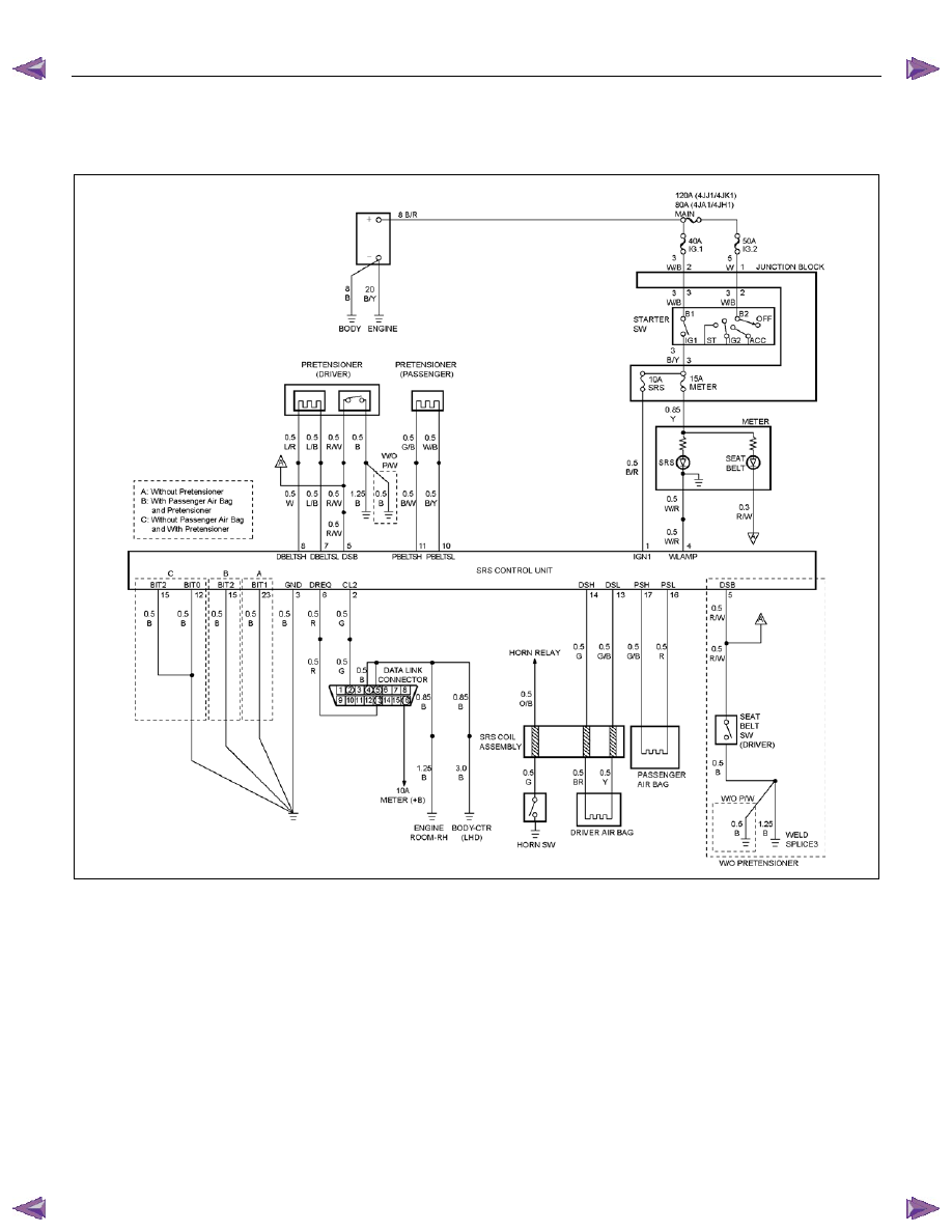
DTC B0029 (Flash Code 29) Passenger Pretensioner Squib Circuit High
Resistance
RTW79ALF000301
Circuit Description
When the ignition switch is turned “ON”, the SRS
control unit will perform tests to diagnose critical
malfunctions within itself. Upon passing these tests
“Ignition 1”, and deployment loop voltages are
measured to ensure they are within their respective
normal voltage ranges. The SRS control unit then
proceeds with the “Resistance Measurement Test”.
“Passenger Pretensioner Low” terminal “10” is
grounded through a resister and the passenger current
source connected to “Passenger Pretensioner High”
terminal “11” allows a known amount of current to flow.
By monitoring the voltage difference between
“Passenger Pretensioner High” and “Passenger
Pretensioner Low” the SRS control unit calculates the
combined resistance of the passenger pretensioner
assembly, harness wiring circuits “Passenger
Pretensioner High” and “Passenger Pretensioner Low”
connector terminal contact.

RESTRAINT CONTROL SYSTEM 9A1-41
DTC Will Set When
The combined resistance of the passenger air
pretensioner assembly, harness wiring circuits
“Passenger Pretensioner High” and “Passenger
Pretensioner Low”, and connector terminal contact is
above a specified value. This test is run once each
ignition cycle during the “Resistance Measurement
Test” when:
1. No “higher priority faults” are detected during “Turn–
ON”,
2. “Ignition 1” voltage is in the specified value.
Action Taken
SRS control unit turns “ON” the “AIR BAG” warning
lamp and sets a diagnostic trouble code.
DTC Will Clear When
The ignition switch is at “LOCK”.
DTC Chart Test Description
Number(s) below refer to step number(s) on the
diagnostic chart:
2. This test determines whether the malfunction is in
the SRS control unit.
3. This test verifies proper connection of the yellow
connector.
4. This test checks for proper contact and/or corrosion
of the yellow connector terminals.
5. The test checks for a malfunctioning passenger
pretensioner assembly.
6. This test determines whether the malfunction is due
to high resistance in the wiring.
Diagnostic Aids
An intermittent condition is likely to be caused by a poor
connection at the passenger pretensioner assembly
harness connector terminals “1” and “2”, SRS control
unit terminal “11” and “10”, or a poor wire to terminal
connection in circuits “Passenger Pretensioner High”
and “Passenger Pretensioner Low”. This test for this
diagnostic trouble code is only run while the “AIR BAG”
warning lamp is performing the bulb check. When a
scan tool “Clear Codes” command is issued and the
malfunction is still present, the DTC will not reappear
until the next ignition cycle.
Нет комментариевНе стесняйтесь поделиться с нами вашим ценным мнением.
Текст