Isuzu KB P190. Manual — part 62
STEERING SUSPENSION WHEELS AND TIRES
3-1
SECTION 3
STEERING SUSPENSION
TABLE OF CONTENTS
Section 3A Front Alignment . . . . . . . . . . . . . . . . . . . . . . . 249
PAGE
Section 3B Power Assited Steering System . . . . . . . . . . . . . . . ... 262
Section 3C Front Suspension . . . . . . . . . . . . . . . . . . . . . . 320
Section 3D Rear Suspension . . . . . . . . . . . . . . . . . . . . . . 385
Section 3E Wheels and Tires . . . . . . . . . . . . . . . . . . . . . . 405
WHEELS AND TIRES
ISUZU KB P190 2007
FRONT ALIGNMENT 3A-1
SECTION 3A
FRONT ALIGNMENT
TABLE OF CONTENTS
Front End Alignment Inspection and Adjustment . . . . . . . . . . . . . . . 3A-
PAGE
General Description . . . . . . . . . . . . . . . . . . . . . . . . . . 3A-
Inspection . . . . . . . . . . . . . . . . . . . . . . . . . . . . . . 3A- 3
Alignment for 4 2 (except High Ride Suspension) . . . . . . . . . . . . . . 3A-
Alignment for 4 2 (High Ride Suspension) and 4 4 . . . . . . . . . . . . . .. 3A- 10
3A-2 FRONT ALIGNMENT
Front End Alignment Inspection and
Adjustment
General Description
“Front End Alignment” refers to the angular relationship
between the front wheels, the front suspension attaching parts
and the ground.
Proper front end alignment must be maintained in order to
insure efficient steering, good directional stability and to
prevent abnormal tire wear.
The most important factors of front end alignment are wheel
toe-in, wheel camber and axle caster.
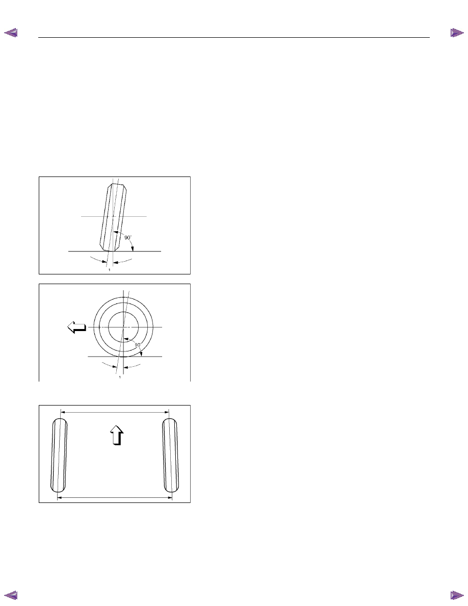
Camber:
This illustration shows a view from the front of the vehicle.
Camber is the vertical tilting inward or outward of the front
wheels. When the wheels tilt outward at the top, the camber is
positive (+). When the wheels tilt inward at the top, the camber
is negative (-). The amount of tilt measured in degrees from
the vertical is called the camber angle (1). If camber is extreme
or unequal between the wheels, improper steering and
excessive tire wear will result. Negative camber causes wear
on the inside of the tire, while positive camber causes wear to
the outside.
Caster:
This illustration shows a view from the side of the vehicle.
Caster (1) is the vertical tilting of the wheel axis either
forward or backward (when viewed from the side of the
vehicle). A backward tilt is positive (+) and a forward tilt is
negative (-). On the short and long arm type suspension
you cannot see a caster angle without a special instrument, but
if you look straight down from the top of the upper control arm
to the ground, the ball joints do not line up (fore and aft) when
a caster angle other than 0 degrees is present. With a positive
angle, the lower ball joint would be slightly ahead (toward the
front of the vehicle) of the upper ball joint center line.
Toe-in:
This illustration shows a view from the top of the vehicle.
Toe-in is the measured amount the front wheels are turned in.
The actual amount of toe-in is normally a fraction of a degree.
Toe-in is measured from the center of the tire treads or from
the inside of the tires. The purpose of toe-in is to insure parallel
rolling of the front wheels and to offset any small deflections of
the wheel support system which occurs when the vehicle is
rolling forward. Incorrect toe-in results in excessive toe-in and
unstable steering. Toe-in is the last alignment to be set in
the front end alignment procedure.
FRONT ALIGNMENT 3A-3
Inspection
Before making any adjustments affecting caster, camber or
toe-in, the following front end inspection should be made.
1. Inspect the tires for proper inflation pressure. Refer to
Main Data and Specifications in Wheel and Tire System
section.
2. Make sure that the vehicle is in an unladen condition (With
no passengers or loading).
3. Make sure that the spare tire is installed at the normal
position.
4. Inspect the front wheel bearings for proper adjustment.
Refer to Front Hub and Disc Overhaul in Suspension
section.
5. Inspect the ball joints and tie rod ends. If excessive
looseness is noted, correct before adjusting. Refer to
Steering Linkage in this section.
6. Inspect the wheel and tires for run-out. Refer to Wheel
Replacement in Wheel and Tire System section.
7. Inspect the trim height. If not within specifications, the
correction must be made before adjusting caster.
8. Inspect the steering unit for looseness at the frame.
9. Inspect shock absorbers for leaks or any noticeable noise.
Refer to Shock Absorber in Suspension section.
10.
Inspect the control arms or stabilizer bar attachment for
looseness. Refer to Suspension section.
11. Inspect the front end alignment using alignment equipment.
Follow the manufacturer’s instructions.
12. Park the vehicle on a level surface.
Нет комментариевНе стесняйтесь поделиться с нами вашим ценным мнением.
Текст