Isuzu KB P190. Manual — part 63
3A-4 FRONT ALIGNMENT
Alignment for 4
××××2 (except High Ride Suspension)
Caster and camber adjustment
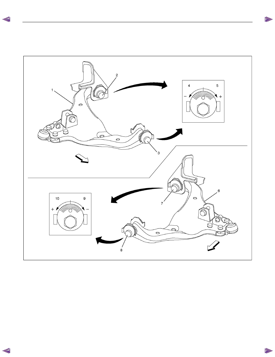
The lower links of the 4 X2 vehicle front suspension have an adjusting cam at either end (front and rear). This
permits simultaneous adjustment of camber and caster angle.
Front
Front
RTW340LF000301
Legend
1. Lower link ASM RH
2. Adjusting cam RR
3. Adjusting cam FRT
4. -direction The lower link ASM moves
toward the inside
5. +direction The lower link ASM moves
toward the outside
6. Lower link ASM LH
7. Adjusting cam RR
8. Adjusting cam FRT
9. -direction The lower link ASM moves
toward the inside
10. +direction The lower link ASM moves
toward the outside
FRONT ALIGNMENT 3A-5
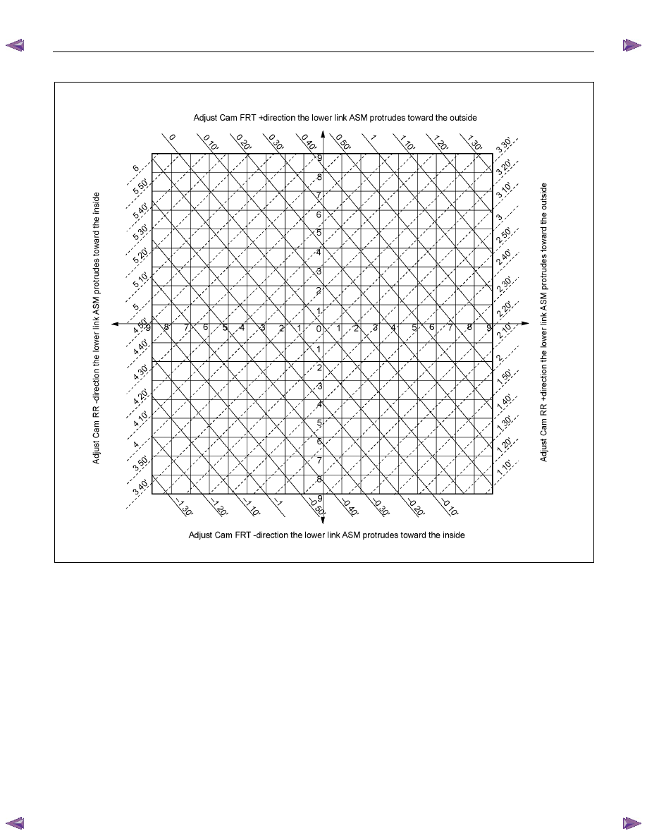
The following illustration shows the alignment procedure.
RTW340LF000401
3A-6 FRONT ALIGNMENT
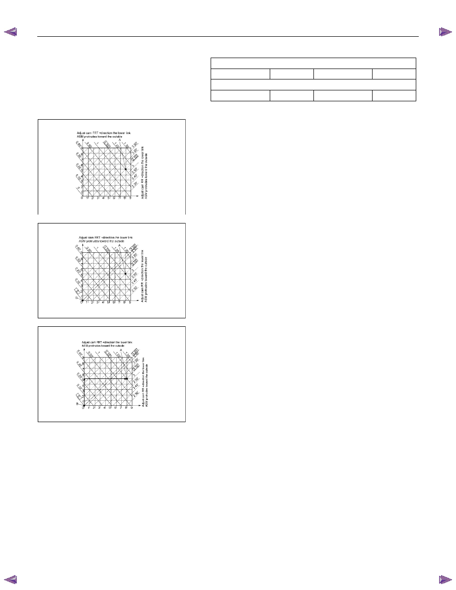
Example
Measured value
Camber angle
1
°10' Caster
angle
3
°10'
Standard value
Camber angle
0
°±30' Caster
angle 3
°35'±45'
RTW340SH001001
1. Mark an ‘A’ at the intersection point of the measured
camber angle value (solid line) and the measured caster
angle value (dotted line).
RTW340SH001101
2. Mark a ‘B’ at the intersection point of the standard camber
angle value (solid line) and the standard caster angle value
(dotted line).
RTW340SH001201
3. The vertical distance between points ‘A’ and ‘B’ represents
the adjustment required at the front cam. The horizontal
distance between points ‘A’ and ‘B’ represents the
adjustment required at the rear cam.
In this example, the front cam would be moved 5
increments to the positive and the rear cam would be
moved 8 increments to the positive.
CAUTION:
Maximum possible adjustment from the center point of the
cams is 9 increments to either side.

FRONT ALIGNMENT 3A-7
CASTER
3
°35'±45'
Note:
Left and right side to be equal within 30'
CAMBER
0
°±30'
Note:
Left and right side to be equal within 30'
KING PIN INCLINATION
12
°30'±30'
Нет комментариевНе стесняйтесь поделиться с нами вашим ценным мнением.
Текст