Isuzu KB P190. Manual — part 1397

Cruise Control – HFV6
Page 8C–10
Tech 2 Data List
The Tech 2 displays the status of certain cruise control system input parameters.
To view the data list:
1
Connect Tech 2 to the data link connector (DLC) and turn on the ignition.
2
On Tech 2 select Body / Powertrain Interface Module / Diagnostic Data Display / Data List.
Tech 2 Parameter
Units Displayed
Typical Display Values
Cruise Cancel Switch
Inactive / Active
Inactive
Cruise Resume Switch
Off / Enabled
Off
Cruise Set Switch
Inactive / Active
Inactive
Cruise Main Switch
Inactive / Active
Inactive
Cruise Control Set Lamp
Off / On
Off
Cruise Control On Lamp
Off / On
Off
3
On Tech 2 select Engine / V6 Engine / Data Display / Data List / Cruise Control Data.
Tech 2 Parameter
Units Displayed
Typical Display Values
Brake Lamp Switch
Inactive / Active
Inactive
Initial Brake Apply Sig
Inactive / Active
Inactive
Cruise Set / Decel Swit
Inactive / Active
Inactive
Cruise Resume / Accelerat
Inactive / Active
Inactive
Cruise Control Disengag
Engine Speed / Brake
Engine Speed
4
On Tech 2 select Engine / V6 Engine / Data Display / Data List / Engine Data 1.
Tech 2 Parameter
Units Displayed
Typical Display Values
Clutch Pedal Switch
Inactive / Active
Inactive
2.2 Diagnostic
Systems
Check
Diagnostic Systems Check
Refer to 2.3
Wiring Diagram to aid in the diagnosis of the cruise control system.
For the cruise control system to work effectively the following systems / components need to be serviceable:
Step Action
Yes
No
1
Is the fault specifically isolated to this system / module?
Go to Step 2
Go to 6E1
Powertrain Interface
Module – V6
2
1
Connect Tech 2 to the DLC.
2
Ignition ON, engine OFF.
3
On Tech 2 select
Body / Powertrain Interface Module / Diagnostic Trouble
codes / Read DTCs’.
Are there any set DTC’s?
Go to the
appropriate DTC
table in 6E1
Powertrain Interface
Module – V6.
Go to Step 3

Cruise Control – HFV6
Page 8C–11
Step Action
Yes
No
3
On Tech 2 select
Engine / V6 Engine / Diagnostic Trouble codes / Read DTCs’.
Are there any set DTC’s?
Go to the
appropriate DTC
table in 6C1-2
Engine
Management – V6 –
Diagnostics
Go to Step 4
4
Is the instrument cluster assembly functioning correctly?
Go to 2.4
Cruise
Control Inoperative /
Malfunctioning
Refer to 8A
Electrical – Body
and Chassis.
When all diagnosis and repairs are completed, clear all DTCs and check the system for correct operation.
Cruise Control – HFV6
Page 8C–12
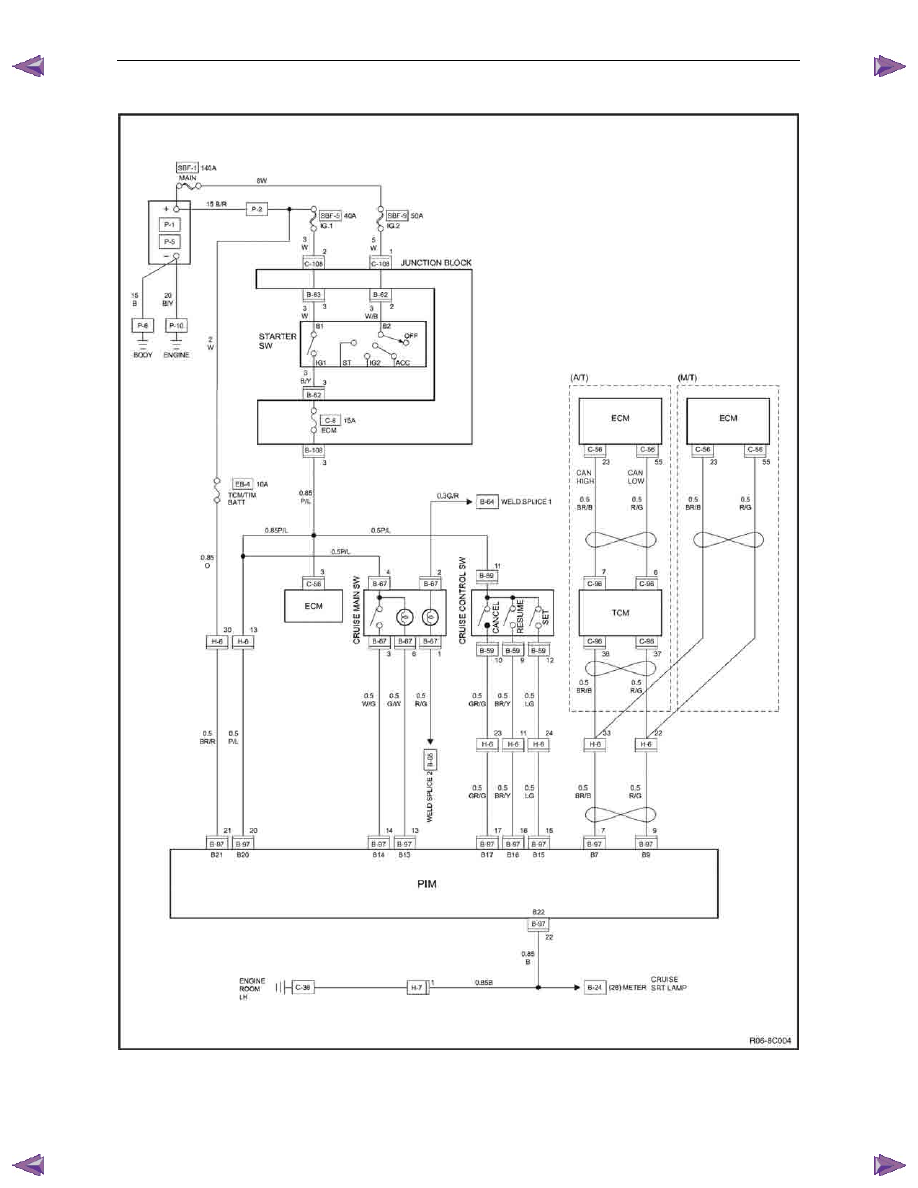
2.3 Wiring
Diagrams
Figure 8C – 6
Cruise Control – HFV6
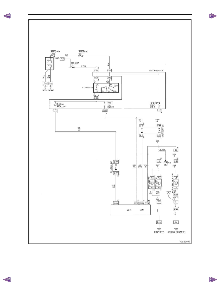
Page 8C–13
Figure 8C – 7
Нет комментариевНе стесняйтесь поделиться с нами вашим ценным мнением.
Текст