Isuzu KB P190. Manual — part 1396
Cruise Control – HFV6
Page 8C–6
The stop lamp switch contacts are normally open with the brake pedal at rest and close when the brake pedal is pressed
turning on the vehicles brake lamps. These switch contacts also double as the cruise cancel signal for the cruise control
operation.
The cruise control initial brake apply signal function switch contacts are normally closed with the brake pedal at rest and
open when the brake pedal is pressed. This switch function is a safety requirement of the vehicle as it ensures that the
cruise control cannot be activated without the brake pedal first being pressed.
Powertrain Interface Module
The Powertrain Interface Module (PIM) is located on the driver’s side, kick trim panel. The purpose of the PIM is to act as
an interface between the drivetrain serial data bus (GMLAN protocol) and the body side data bus (UART Bus protocol).
All inputs from the cruise control switch assembly are directly wired to the PIM. The PIM then takes these inputs,
converts them to GMLAN protocol and sends the messages via the data bus to the engine control module (ECM). The
PIM also receives signals for the cruise control system from the ECM. When the ECM activates cruise control, it sends a
signal through the PIM (which converts it from GMLAN to UART protocol) to display the various cruise control messages
on the instrument cluster assembly.
For further information on the operation of the PIM, refer to 6E1 Powertrain Interface Module – V6.
Engine Control Module
The Engine Control Module (ECM) is mounted on the front of the engine. The role of the ECM is to receive all the inputs
from various sensors (vehicle speed (VSS) etc.) and switches to manage the engine. When a request is sent from the
cruise control switch assembly via the PIM to the ECM, the ECM will activate cruise control providing given parameters
are satisfied. Once the cruise is set, the ECM monitors the vehicle speed and controls the throttle actuator assembly thus
controlling the speed of the vehicle.
For further information on the operation of the ECM, refer to 6C1-1 Engine Management – V6 – General Information.
Throttle Actuator Control (TAC) Assembly
The throttle actuator control assembly is located on the front of the inlet manifold. The throttle actuator control assembly
receives signals from the ECM and controls the angle of the throttle plate. Refer to 6C1-1 Engine Management – V6 –
General Information for further information.
1.3
System Operation
Preliminary Information
Enabled and Disabled
The cruise control is enabled / disabled by pressing the cruise control ON–OFF switch mounted on the lower right hand
side of the dash panel. When cruise control is enabled, the cruise control ON–OFF switch illuminates and the cruise
control is ready for a speed to be set (cruise control activated). When the cruise control is disabled, the cruise control
cannot be activated.
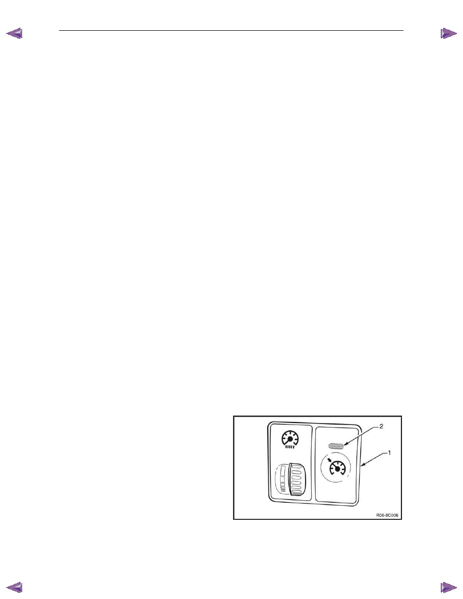
Cruise Enabled
1
The cruise control ON–OFF switch (1) supplies 12
Volts to the Powertrain Interface Module (PIM) when it
is pressed.
2
The cruise control ON–OFF switch lamp (2) turns on.
Cruise Disabled
1
When cruise control ON–OFF switch (1) is pressed
again, power is removed from the PIM disabling the
cruise control.
2
The cruise control ON–OFF switch lamp (2) turns off.
Figure 8C – 4
Cruise Control – HFV6
Page 8C–7
Activated and Deactivated
When the cruise control is enabled, the vehicle speed must be above 40 km/h and the cruise control switch assembly
pressed to SET–COAST, the cruise control will be activated and the vehicle will maintain the set speed. When
deactivated by the methods described within this section, the vehicle will no longer maintain the set speed, but the cruise
control will still be engaged.
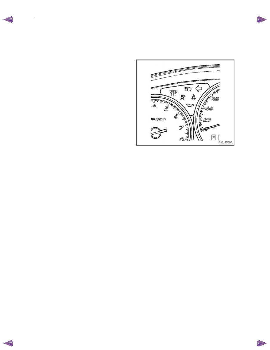
Cruise Active
When the cruise control is activated via the cruise control
switch assembly, the cruise set warning lamp will illuminate
the instrument cluster assembly.
Cruise Deactivated
Upon receiving a signal to deactivate the cruise control the
ECM will provide a signal to the instrument cluster, via the
PIM, to inform the user the cruise control is deactivated.
When the cruise control is deactivated via the cruise control
switch assembly, the brake pedal, or the clutch pedal, the
cruise set warning lamp will turn OFF within the instrument
cluster assembly.
Figure 8C – 5
Enabling the Cruise Control
Refer to 2.3
Wiring Diagrams for the following description.
When the cruise control ON-OFF button is pressed, 12 V is applied to the powertrain interface module (PIM) connector
B – 97 pin 14. This informs the PIM the user has requested the cruise control function be engaged or disengaged. This
signal is then output by the PIM as GM LAN protocol along the bus to the engine control module (ECM). The ECM
recognises the command from the PIM to engage the cruise control. The PIM then provides a ground signal to B – 97 pin
13 the cruise control ON-OFF switch indicator lamp, to inform the user the cruise control is engaged.
Brake Before Cruise
Before the cruise control can be activated the driver must have applied the brakes and the system received a valid
response at least once per ignition cycle. If the driver manages to drive the vehicle without having used the brakes before
pressing the cruise control ON–OFF button, the cruise control cannot be activated.
Activating the Cruise Control
The user activates the cruise control at a desired speed above 40 km/h by pressing the cruise control switch assembly
SET–COAST button. This provides a 12 V signal to the PIM through connector B – 97 pin 15. The PIM then outputs this
signal as GM LAN protocol through the data bus to the ECM. If the ECM already has cruise control engaged, upon
receipt of the message from the PIM, the ECM will activate cruise control and set the speed. The ECM receives all the
various inputs required to maintain the correct speed and then controls the throttle actuator control assembly depending
on the load on the engine (ascending or descending hills, etc).
Deactivating the Cruise Control
When the cruise control is activated, it can be deactivated by any of the following:
Pressing the Brake Pedal
When the brake pedal is pressed, two signals are sent directly to the ECM by the circuits from the brake pedal switch
assembly. The cruise cancel circuit will open (normally closed) thus dropping the supply voltage from the ECM connector
C – 56 pin 46. Simultaneously, the stop lamp circuit will close (normally open) and supply 12 V to the ECM at connector
C – 56 pin 10. This is a double redundancy system so that if either switch or circuit from the brake pedal switch assembly
fails, the cruise control will still be deactivated.

Cruise Control – HFV6
Page 8C–8
Pressing the Cruise ON–OFF Button
Pressing the cruise control switch assembly ON–OFF button will send a signal via the PIM to the ECM to deactivate the
cruise control.
Rotating the Cruise Control Switch Assembly
Rotating the cruise control switch assembly to the CANCEL position will send a signal via the PIM to the ECM to
deactivate the cruise control.
Pressing the Clutch Pedal (Manual Vehicles Only)
When the clutch pedal is pressed, the cruise control cancel circuit will open (normally closed) thus removing the supply
voltage from the ECM connector C – 56 pin 53. The ECM then deactivates the cruise control.
Decelerating While Cruise Control is Activated
When the cruise control is activated, the speed can be reduced by pressing and holding the cruise control switch
assembly to SET–COAST. When this is done, 12 V is applied to PIM connector B – 97 pin 15. The PIM will then translate
the command to GM LAN protocol and sends the request to the ECM to reduce the speed. The ECM will then
temporarily disable the cruise control and close the throttle plate. The vehicle should then start to decelerate. Once the
operator releases the cruise control switch assembly, the ECM will receive this signal through the PIM and will then set
the speed according to the current VSS and maintain that speed.
Resuming a Speed After Cruise Control Has Been Deactivated
If the cruise control system is engaged but deactivated, the last speed at which it was activated can be resumed. Turning
the cruise control switch assembly to RES–ACC will apply 12 V to the PIM at connector B – 97 pin 16. The PIM will then
translate the command to GM LAN protocol and transmit the request to the ECM. The ECM will then recall the last stored
speed at which the cruise control was activated and increase or reduce engine RPM to maintain that speed.
Accelerating While Cruise Control is Activated
Using the Cruise Control Switch Assembly
When the cruise control is active, rotating the cruise control switch assembly to RES–ACC will accelerate the vehicle.
The cruise control switch assembly will supply a 12 V signal to the PIM connector B – 97 pin 16, which is continuous as
long as the switch is held. While the PIM is receiving the 12 V signal, it will continuously transmit to the ECM to
accelerate the vehicle. The ECM will open the throttle plate to accelerate the vehicle. When the desired speed is
achieved and the cruise control switch assembly is released, the ECM will maintain the vehicle at that speed.
Pressing the Accelerator Pedal
When the cruise control is active, pressing the accelerator pedal will accelerate the vehicle.
Once pressure is removed from the accelerator pedal, the vehicle will return to the last stored speed at which the cruise
control was activated and control the throttle plate to maintain that speed.

Cruise Control – HFV6
Page 8C–9
2 Diagnostics
2.1
Diagnostic General Information
Basic Knowledge Required
A lack of basic understanding regarding
electronics, electrical wiring circuits and use
of electrical circuit testing tools when
performing the cruise control diagnostic
procedures could result in incorrect
diagnostic results or damage to components.
A general understanding of basic electronics, electrical wiring circuits and the correct use of the basic electrical circuit
testing tools is required to perform the diagnostic procedures detailed in this Section. Refer to 8A Electrical – Body and
Chassis Wiring Diagrams for information on electrical circuits.
In addition, a general understanding of the cruise control and its component operation is essential to prevent
misdiagnosis and component damage.
Basic Diagnostic Tools Required
Use of incorrect electrical circuit diagnostic
tools when performing the cruise control
diagnostic procedures could result in
incorrect diagnostic results or damage to
components.
The following electrical circuit testing tools are required to perform the diagnostic procedures detailed in this Section:
•
test lamp,
•
digital multimeter with 10 meg ohms impedance, and
•
connector test adapter kit Tool No. KM609.
For further information on the use of these tools, refer to 8A Electrical – Body and Chassis Wiring Diagrams.
Нет комментариевНе стесняйтесь поделиться с нами вашим ценным мнением.
Текст