Isuzu KB P190. Manual — part 1105
7A2-136 TRANSMISSION CONTROL SYSTEM (JR405E)
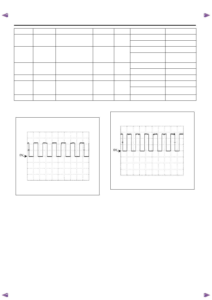
Reference Wave form
Engine speed signal
• Measurement terminal: 7 of C-94 (+) & 5 of C-95 (-
)
• Measurement scale: 5 volts/div & 10 ms/div
• Measurement condition: Engine run at 2000 RPM
Vehicle speed signal
• Measurement terminal: 10 of C-94 (+) & 5 of C-95
(-)
• Measurement scale: 5 volts/div & 50 ms/div
• Measurement condition: Vehicle run at 20 km/h (12
MPH)
19 of C-95
RED/ YEL
R range switch signal
19 of C-95
Ground
R range
Nearly 12 volts
Other than R range
Less than 2 volts
20 of C-95
WHT/ BLK
High clutch TFP switch
signal
20 of C-95
(back probe)
Ground
3rd or 4th gear
Less than 2 volts
Other than 3rd to 4th
gear
Nearly 12 volts
21 of C-95
PNK/ BLU
L range switch signal
21 of C-95
Ground
L range
Nearly 12 volts
Other than L range
Less than 2 volts
22 of C-95
GRY/ RED
Ground return
22 of C-95
Ground
Ignition OFF
Continuity
23 of C-95
VIO
PC solenoid control
23 of C-95
(back probe)
5 of C-95
(back
probe)
P or N rage
Nearly 12 volts
D range
Less than 2 volts
24 of C-95
WHT
Ignition voltage
24 of C-95
Ground
Ignition switch ON
Nearly 12 volts
Pin No.
Wire color
Pin function
DMM (+)
DMM (-)
Test condition
Standard value

TRANSMISSION CONTROL SYSTEM (JR405E) 7A2-137
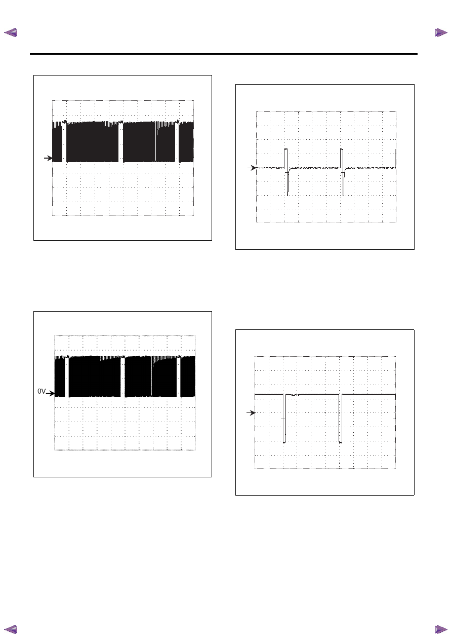
Input shaft speed (ISS) sensor signal
• Measurement terminal: 3 of C-95 (+) & 5 of C-95 (-
)
• Measurement scale: 5 volts/div & 500 micro sec./
div
• Measurement condition: Vehicle run at 20 km/h (12
MPH) in L range with 1st gear
Output shaft speed (OSS) sensor signal
• Measurement terminal: 13 of C-95 (+) & 5 of C-95
(-)
• Measurement scale: 5 volts/div & 5 ms/div
• Measurement condition: Vehicle run at 20 km/h (12
MPH) in L range with 1st gear
Low & reverse brake solenoid valve control signal
• Measurement terminal: 6 of C-95 (+) & 22 of C-95
(-)
• Measurement scale: 5 volts/div & 10 ms/div
• Measurement condition: P or N range
2-4 brake solenoid valve control signal
• Measurement terminal: 7 of C-95 (+) & 22 of C-95
(-)
• Measurement scale: 5 volts/div & 10 ms/div
• Measurement condition: P or N range
0V
0V
0V
0V
7A2-138 TRANSMISSION CONTROL SYSTEM (JR405E)
High clutch solenoid valve control signal
• Measurement terminal: 8 of C-95 (+) & 22 of C-95
(-)
• Measurement scale: 5 volts/div & 10 ms/div
• Measurement condition: P or N range
Low clutch solenoid valve control signal
• Measurement terminal: 9 of C-95 (+) & 22 of C-95
(-)
• Measurement scale: 5 volts/div & 10 ms/div
• Measurement condition: D range with 4th gear
Torque converter clutch (TCC) solenoid valve
control signal
• Measurement terminal: 17 of C-95 (+) & 5 of C-95
(-)
• Measurement scale: 10 volts/div & 5 ms/div
• Measurement condition: TCC is commanded OFF
Torque converter clutch (TCC) solenoid valve
control signal
• Measurement terminal: 17 of C-95 (+) & 5 of C-95
(-)
• Measurement scale: 10 volts/div & 5 ms/div
• Measurement condition: TCC is commanded ON
0V
0V
0V
TRANSMISSION CONTROL SYSTEM (JR405E) 7A2-139
Repair Instructions
Transmission Controls Module (TCM) Replacement
Description
The following A - C steps provide an overview
procedure to replace and reprogram a TCM. Each A -C
steps is explained further in this section.
A. Replace the old TCM with the new TCM.
B. Program the latest software and calibrations into the
new TCM using the Service Programming System
(SPS) if released. If not released, do not perform this
and skip to Step C.
C. Program the vehicle identification number (VIN) into
the TCM.
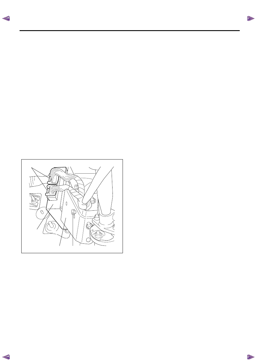
A. Removal and Installation
Removal Procedure
1. Disconnect the negative battery cable.
2. Disconnect the TCM harness connectors (1).
3. Loosen nuts (2) and remove the TCM (3) from the
bracket (4).
Installation Procedure
Follow the removal steps in the reverse order. Be sure
that the connectors are securely fastened.
B. Programming Software and Calibrations
Program the latest software/ calibrations if released.
Refer to Service Programming System (SPS)
Description and SPS (Remote Procedure) or SPS
(Pass-Thru Procedure) in this section. If not released,
do not perform this and skip to Step C.
C. Programming Vehicle Identification Number
(VIN)
Notice: If you have performed SPS in the previous
step, VIN has prgrommaned already. Programming VIN
is not necessary in this step.
1. Install a scan tool.
2. Turn ON the ignition, with the engine OFF.
3. Select Diagnostics > appropriate vehicle
identification > AT JR405E > Programming >
Program VIN.
4. If you installed a new, skip to step 8. If you installed
a reused TCM from another vehicle or incorrect
VIN is programmed before, the TCM might be
locked already. In order to get programming
approval, the on-screen displays a message to
user. Get programming approval from the TIS
2000 using the following procedure:
a. Connect a scan tool to the terminal that
installed TIS 2000 with the latest software and
the hardware key is plugged into port.
b. Turn ON the scan tool and keep at title screen.
c. Launch the TIS application.
d. Select the Security Access at the main screen.
e. Highlight the “Tech 2" on the Diagnostic Tool
Selection screen and click “Next”.
f. Click “Close” on the Security Access Enabled
screen.
g. Turn OFF the scan tool.
h. Disconnect the scan tool from the terminal.
5. Install a scan tool to the vehicle.
6. Turn ON the ignition, with the engine OFF.
7. Select Diagnostics > appropriate vehicle
identification > AT JR405E > Programming >
Program VIN.
8. Input 17 digits of correct VIN.
9. After complete the programming, turn OFF/ ON the
ignition.
10. Select Diagnostics > Lock ECU.
11. Follow the on-screen instructions and turn OFF/
ON the ignition.
Service Programming System (SPS)
Description
The service programming system (SPS) allows a
technician to program a control module through the
data link connector (DLC). The information transfer
circuit that is used at the DLC is the same serial data
circuit used by the scan tool for retrieving DTCs,
displaying data, clearing DTCs etc. This procedure
offers the ability to install software/ calibrations
matched to a particular vehicle.
Most control modules have two types of memory. The
software/ calibrations reside in the flash memory. The
two types of memory are listed below:
1
3
4
2
Нет комментариевНе стесняйтесь поделиться с нами вашим ценным мнением.
Текст