Isuzu KB P190. Manual — part 1104
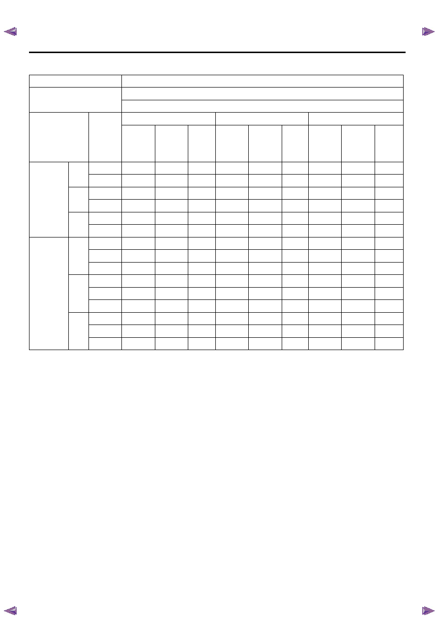
7A2-132 TRANSMISSION CONTROL SYSTEM (JR405E)
Shift Speed Table
Euro 3 specification engine
Final gear ratio & tire size
41/11 (3.727) & 215/70R15
43/10 (4.300) & 245/70R16
Gear
Accel.
pedal
position
(%)
Normal mode
Power drive mode
4L mode
Vehicle
speed
(km/h)
Vehicle
speed
(MPH)
Output
shaft
speed
(RPM)
Vehicle
speed
(km/h)
Vehicle
speed
(MPH)
Output
shaft
speed
(RPM)
Vehicle
speed
(km/h)
Vehicle
speed
(MPH)
Output
shaft
speed
(RPM)
Upshift
1-2
50
27-34
16-20
930
31-38
19-23
1054
30-37
18-22
1023
100
38-45
23-27
1271
38-45
23-27
1271
34-41
20-25
1147
2-3
50
49-57
29-34
1612
58-66
35-40
1891
55-63
33-38
1798
100
72-80
43-48
2325
72-80
43-48
2325
71-79
43-47
2294
3-4
50
87-96
52-58
2790
97-106
58-64
3099
84-93
50-56
2697
100
113-123
68-74
3595
113-123
68-74
3595
113-123
68-74
3595
Downshift
4-3
0
29-36
17-22
992
29-36
17-22
992
29-36
17-22
992
50
66-74
40-44
2139
74-82
44-49
2387
71-79
43-47
2294
100
108-117
65-70
3440
108-117
65-70
3440
98-107
59-64
3130
3-2
0
6-12
4-7
279
6-12
4-7
279
6-12
4-7
279
50
30-37
18-22
1023
47-55
28-33
1550
45-53
27-32
1488
100
67-75
40-45
2170
67-75
40-45
2170
59-67
35-40
1922
2-1
0
6-12
4-7
279
6-12
4-7
279
6-12
4-7
279
50
10-16
6-10
403
19-26
11-16
682
18-25
11-15
651
100
29-36
17-22
992
29-36
17-22
992
27-34
16-20
930

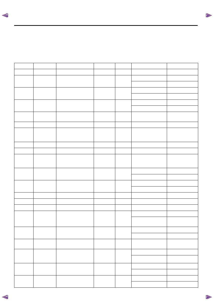
TRANSMISSION CONTROL SYSTEM (JR405E) 7A2-133
Except Euro 3 specification engine
Final gear ratio & tire size
41/11 (3.727) & 215/70R15
43/10 (4.300) & 245/70R16
Gear
Accel.
pedal
position
(%)
Normal mode
Power drive mode
4L mode
Vehicle
speed
(km/h)
Vehicle
speed
(MPH)
Output
shaft
speed
(RPM)
Vehicle
speed
(km/h)
Vehicle
speed
(MPH)
Output
shaft
speed
(RPM)
Vehicle
speed
(km/h)
Vehicle
speed
(MPH)
Output
shaft
speed
(RPM)
Upshift
1-2
50
27-34
16-20
930
31-38
19-23
1054
30-37
18-22
1023
100
35-42
21-25
1178
35-42
21-25
1178
34-41
20-25
1147
2-3
50
49-57
29-34
1621
58-66
35-40
1891
55-63
33-38
1798
100
70-78
42-47
2263
70-78
42-47
2263
71-79
43-47
2294
3-4
50
87-96
52-58
2790
97-106
58-64
3099
84-93
50-56
2697
100
109-119
65-71
3471
109-119
65-71
3471
113-123
68-74
3595
Downshift
4-3
0
39-36
23-22
992
29-36
17-22
992
29-36
17-22
992
50
66-74
40-44
2139
74-82
44-49
2387
71-79
43-47
2294
100
104-113
62-68
3316
104-113
62-68
3316
98-107
59-64
3130
3-2
0
6-12
4-7
279
6-12
4-7
279
6-12
4-7
279
50
30-37
18-22
1023
47-55
28-33
1550
45-53
27-32
1488
100
65-73
39-44
2108
65-73
39-44
2108
59-67
35-40
1922
2-1
0
6-12
4-7
279
6-12
4-7
279
6-12
4-7
279
50
10-16
6-10
403
19-26
11-16
682
18-25
11-15
651
100
29-36
17-22
992
29-36
17-22
992
27-34
16-20
930
7A2-134 TRANSMISSION CONTROL SYSTEM (JR405E)
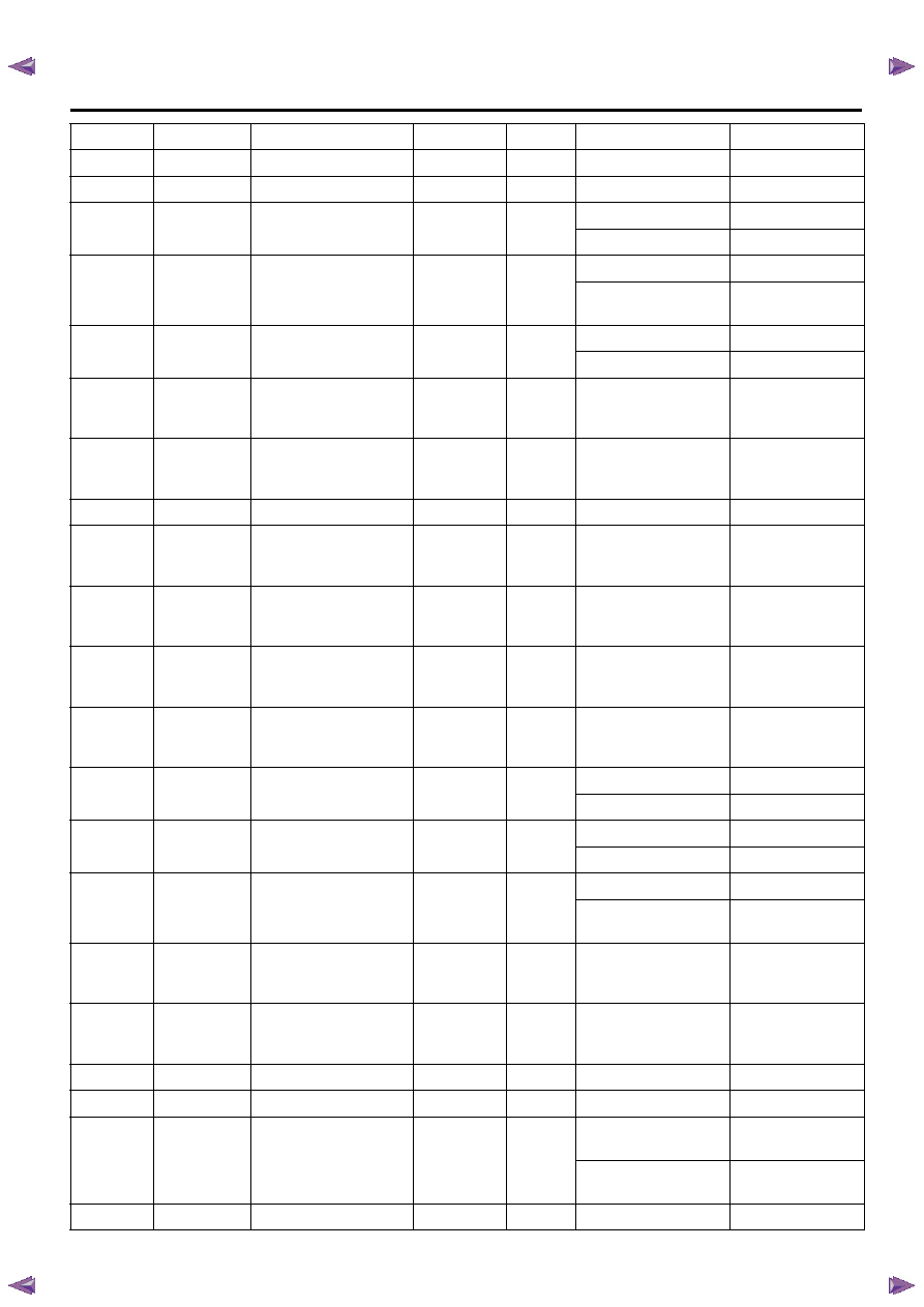
TCM Signal Test
Inspection Tool
Use a DMM to measure voltage and circuit continuity.
Also use an oscilloscope to measure waveform. Refer
to the following table for the specified ranges or
reference waveform.
Since the TCM terminals are extremely small, use
appropriate test adapter from the test adapter kit. This
will make measurement easier.
Pin No.
Wire color
Pin function
DMM (+)
DMM (-)
Test condition
Standard value
1 of C-94
RED/ WHT
Battery voltage
1 of C-94
Ground
Any time
Nearly 12 volts
2 of C-94
YEL/ VIO
P range switch signal
2 of C-94
Ground
P range
Nearly 12 volts
Other than P range
Less than 2 volts
3 of C-94
RED
Brake pedal switch
signal
3 of C-94
Ground
Pedal is released
Less than 2 volts
Pedal is applied
Nearly 12 volts
4 of C-94
PNK/ WHT
3rd start lamp control
4 of C-94
(back probe)
Ground
Lamp OFF
Nearly 12 volts
Lamp ON
Less than 2 volts
5 of C-94
VIO/ GRN
Keyword serial data
communication
5 of C-94
7 of B-58
Ignition OFF
Continuity
6 of C-94
—
Not used
—
—
—
—
7 of C-94
BLK/ RED
Engine speed signal
input
7 of C-94
(back probe)
5 of C-95
(back
probe)
Engine run at 2000
RPM
Nearly 6.2 volts by
AC range or
waveform
8 of C-94
—
Not used
—
—
—
—
9 of C-94
—
Not used
—
—
—
—
10 of C-94
BLK/ YEL
Vehicle speed signal
output (2WD)
10 of C-94
(back probe)
5 of C-95
(back
probe)
Vehicle run at 20 km/h
(12 MPH)
Nearly 6.5 volts by
AC range or
waveform
11 of C-94
GRN/ WHT
3rd start switch signal
11 of C-94
(back probe)
Ground
Switch is released
Nearly 12 volts
Switch is pressed
Less than 2 volts
12 of C-94
BLU/ WHT
4WD low signal output
12 of C-94
(back probe)
Ground
4L mode
Less than 2 volts
Other than 4L
Nearly 12 volts
13 of C-94
—
Not used
—
—
—
—
14 of C-94
—
Not used
—
—
—
—
15 of C-94
—
Not used
—
—
—
—
16 of C-94
RED/ WHT
Accelerator pedal
position (APP) signal
input
16 of C-94
(back probe)
5 of C-95
Pedal is released (0%)
Off duty ratio 10%
Pedal is fully applied
(100%)
Off duty ratio 90%
17 of C-94
BLK/GRN
3 range switch signal
17 of C-94
Ground
3 range
Nearly 12 volts
Other than 3 range
Less than 2 volts
18 of C-94
YEL/ BLK
Diagnostic request
switch
5 of C-94
11 of B-
58
Ignition OFF
Continuity
19 of C-94
ORN/ BLU
Transmission oil
temperature lamp
control
19 of C-94
(back probe)
Ground
Lamp OFF
Nearly 12 volts
Lamp ON
Less than 2 volts
20 of C-94
GRY/ YEL
Check trans lamp
control
20 of C-94
(back probe)
Ground
Lamp OFF
Nearly 12 volts
Lamp ON
Less than 2 volts
21 of C-94
PNK
Power drive lamp
control
21 of C-94
(back probe)
Ground
Lamp OFF
Nearly 12 volts
Lamp ON
Less than 2 volts
TRANSMISSION CONTROL SYSTEM (JR405E) 7A2-135
22 of C-94
—
Not used
—
—
—
—
23 of C-94
—
Not used
—
—
—
—
24 of C-94
GRN/ YEL
Power drive switch
signal
24 of C-94
(back probe)
Ground
Switch is OFF
Nearly 12 volts
Switch is ON
Less than 2 volts
1 of C-95
RED/ YEL
2-4 brake TFP switch
signal
1 of C-95
(back probe)
Ground
2nd or 4th gear
Less than 2 volts
Other than 2nd or 4th
gear
Nearly 12 volts
2 of C-95
PNK/ BLK
2 range switch signal
2 of C-95
Ground
2 range
Nearly 12 volts
Other than 2 range
Less than 2 volts
3 of C-95
BRN/ RED
ISS sensor signal
3 of C-95
(back probe)
5 of C-95
(back
probe)
Vehicle run at 20 km/h
(12 MPH) in L range
with 1st gear
Nearly 6.5 volts by
AC range or
waveform
4 of C-95
BLU
TFT sensor signal
4 of C-95
14 of C-
95
Ignition OFF
Refer to
Temperature vs.
Resistance table
5 of C-95
BLK
Ground
5 of C-95
Ground
Ignition OFF
Continuity
6 of C-95
BLU/ BLK
Low & reverse brake
solenoid control
6 of C-95
(back probe)
22 of C-
95 (back
probe)
P or N range
Nearly 6.2 volts by
AC range or
waveform
7 of C-95
BLK/ YEL
2 & 4 brake solenoid
control
7 of C-95
(back probe)
22 of C-
95 (back
probe)
P or N range
Nearly 6.2 volts by
AC range or
waveform
8 of C-95
RED
High clutch solenoid
control
8 of C-95
(back probe)
22 of C-
95 (back
probe)
P or N range
Nearly 6.2 volts by
AC range or
waveform
9 of C-95
WHT/ BLU
Low clutch solenoid
control
9 of C-95
(back probe)
22 of C-
95 (back
probe)
D range with 4th gear
Nearly 6.2 volts by
AC range or
waveform
10 of C-95
RED/ BLK
N range switch signal
10 of C-95
Ground
2 range
Nearly 12 volts
Other than 2 range
Less than 2 volts
11 of C-95
BLU
D range switch signal
11 of C-95
Ground
D range
Nearly 12 volts
Other than 2 range
Less than 2 volts
12 of C-95
YEL
Low & reverse brake
TFP switch
12 of C-95
(back probe)
Ground
R range or L range
Less than 2 volts
Other than R range or
L range
Nearly 12 volts
13 of C-95
YEL/ RED
OSS sensor signal
13 of C-95
(back probe)
5 of C-95
(back
probe)
Vehicle run at 20 km/h
(12 MPH) in L range
with 1st gear
Nearly 6.8 volts by
AC range or
waveform
14 of C-95
BLU/ BLK
TFT sensor low
reference
4 of C-95
14 of C-
95
Ignition OFF
Refer to
Temperature vs.
Resistance table
15 of C-95
—
Not used
—
—
—
—
16 of C-95
—
Not used
—
—
—
—
17 of C-95
BLK
TCC solenoid control
17 of C-95
(back probe)
5 of C-95
(back
probe)
TCC is commanded
OFF
Waveform
TCC is commanded
ON
Waveform
18 of C-95
WHT
Ignition voltage
18 of C-95
Ground
Ignition switch ON
Nearly 12 volts
Pin No.
Wire color
Pin function
DMM (+)
DMM (-)
Test condition
Standard value
Нет комментариевНе стесняйтесь поделиться с нами вашим ценным мнением.
Текст