Isuzu KB P190. Manual — part 1060
CONSTRUCTION AND FUNCTION 7A1-1
SECTION 7A1
CONSTRUCTION AND FUNCTION (JR405E)
TABLE OF CONTENTS
PAGE
Description . . . . . . . . . . . . . . . . . . . . . . . . . . . . . ..7A1- 3
Construction . . . . . . . . . . . . . . . . . . . . . . . . . . . ...7A1- 3
Main Data and Specification . . . . . . . . . . . . . . . . . . . . . .7A1- 4
Number Plate Location . . . . . . . . . . . . . . . . . . . . . . . ..7A1- 5
Electronic Control Components Location . . . . . . . . . . . . . . . ...7A1- 6
Transmission Control Module (TCM) Peripheral Circuit . . . . . . . . . . .7A1- 7
Structure and Function of Component . . . . . . . . . . . . . . . . . . .7A1- 8
Torque Converter (with Lock-up Function) . . . . . . . . . . . . . . . .7A1- 8
Oil Pump . . . . . . . . . . . . . . . . . . . . . . . . . . . . . .7A1- 9
Input Shaft . . . . . . . . . . . . . . . . . . . . . . . . . . . . ..7A1- 10
Output Shaft . . . . . . . . . . . . . . . . . . . . . . . . . . . ...7A1- 10
Gear Shifting Mechanism . . . . . . . . . . . . . . . . . . . . . . ..7A1- 10
Control Valve . . . . . . . . . . . . . . . . . . . . . . . . . . . ..7A1- 14
Oil Passage . . . . . . . . . . . . . . . . . . . . . . . . . . . . .7A1- 19
Parking Function . . . . . . . . . . . . . . . . . . . . . . . . . . 7A1- 20
Inhibitor Switch . . . . . . . . . . . . . . . . . . . . . . . . . . ..7A1- 21
Turbine Sensor . . . . . . . . . . . . . . . . . . . . . . . . . . ...7A1- 22
Speed Sensor . . . . . . . . . . . . . . . . . . . . . . . . . . . .7A1- 22
Accelerator Pedal Position Sensor . . . . . . . . . . . . . . . . . . ..7A1- 23
Engine Speed Sensor (=CKP Sensor) . . . . . . . . . . . . . . . . . ..7A1- 23
Brake Switch . . . . . . . . . . . . . . . . . . . . . . . . . . . ..7A1- 24
Mode Select Switch . . . . . . . . . . . . . . . . . . . . . . . . ...7A1- 24
Transmission Control Module (TCM) . . . . . . . . . . . . . . . . . ...7A1- 25
Control Mechanism . . . . . . . . . . . . . . . . . . . . . . . . . . 7A1- 26
Content of Function and Control . . . . . . . . . . . . . . . . . . . ..7A1- 26
Control Item, Input and Output . . . . . . . . . . . . . . . . . . . . .7A1- 29
Line Pressure Control . . . . . . . . . . . . . . . . . . . . . . . . 7A1- 30
Lock-up Control . . . . . . . . . . . . . . . . . . . . . . . . . . .7A1- 30
Direct Electric Shift Control (DESC) . . . . . . . . . . . . . . . . . . .7A1- 31
7A1-2 CONSTRUCTION AND FUNCTION
PAGE
Learning Function . . . . . . . . . . . . . . . . . . . . . . . . . ..7A1- 33
Major Input/Output Component and Their Functions . . . . . . . . . . . .7A1- 34
Control Circuit Block Diagram . . . . . . . . . . . . . . . . . . . . ..7A1- 35
Gear Train (Transmission Mechanism) Operation and Hydraulic Circuit . . . . ..7A1- 36
Construction and Operation . . . . . . . . . . . . . . . . . . . . . .7A1- 36
Component Name and Function . . . . . . . . . . . . . . . . . . . ...7A1- 36
Component and Their Operating Condition . . . . . . . . . . . . . . . 7A1- 37
CONSTRUCTION AND FUNCTION 7A1-3
DESCRIPTION
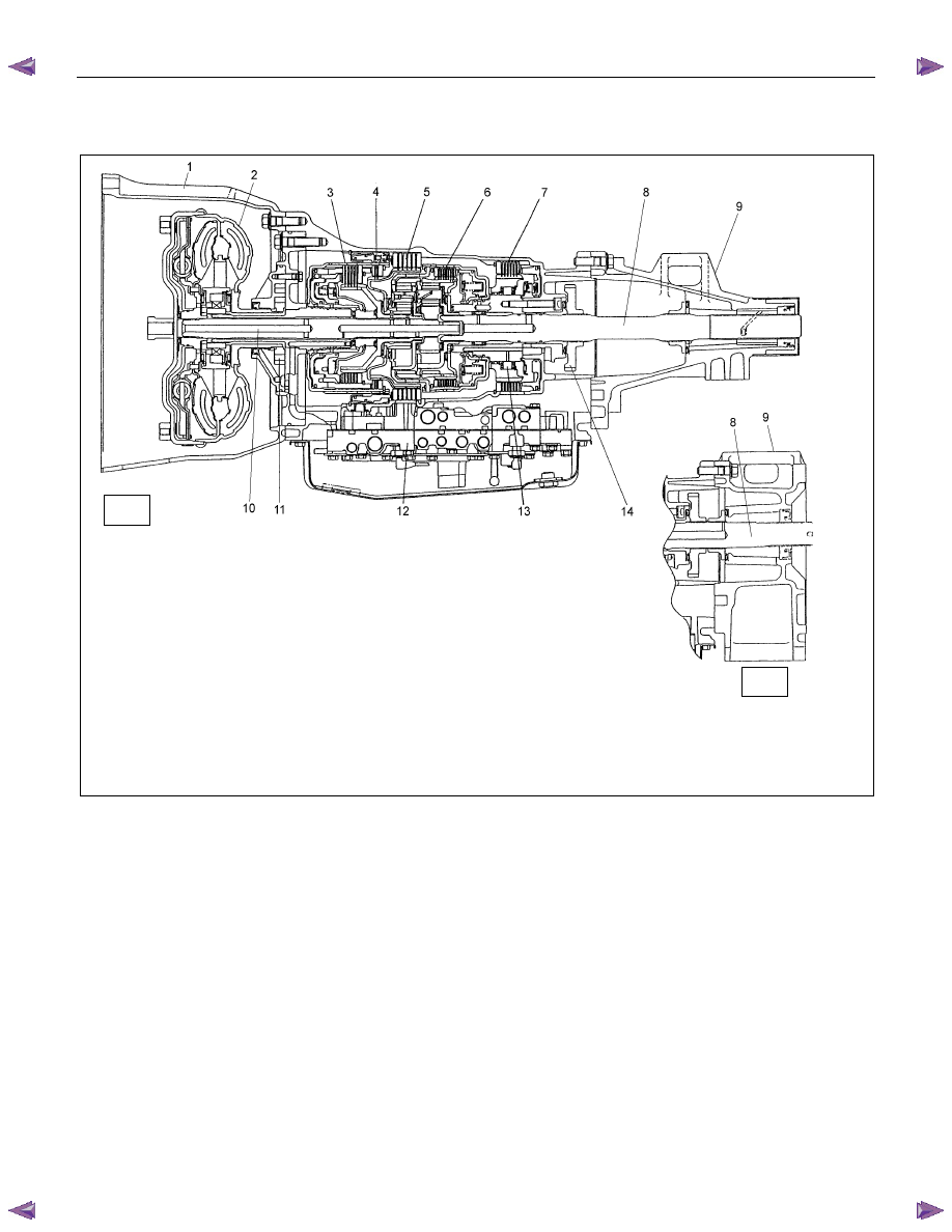
CONSTRUCTION
1
Converter Housing
6 Low Clutch
11 Oil Pump
2
Torque Converter
7 Low & Reverse Brake
12 Control Valve
3
High Clutch
8 Output Shaft
13 Low One-way Clutch
4
Reverse Clutch
9 Extension Housing
14 Parking Gear
5
2-4 Brake
10 Input Shaft
Figure 1. Construction of Automatic Transmission
The JR405E automatic transmission is electrically controlled by a microcomputer transmission control module
(TCM). There are four forward speeds and one reverse speed.
This JR405E automatic transmission employs a clutch pressure direct control system (Direct Electronic Shift
Control: DESC) using duty cycle type solenoids, which ensure high shift quality.
This transmission also has a learning function and constantly checks the time of each clutch and brake
required for the shift in order to match this time with the target value for the optimum shift.
The TCM will automatically select the most appropriate shift points and lock-up points depending on the
Accelerator pedal opening, the vehicle speed and the vehicle load.
If any trouble arises in the speed sensor, APP sensor, solenoid, etc., the fail-safe control function is activated
to keep the running performance.
Problems with the sensors or the solenoids can quickly be detected with the self diagnosis procedure
described in this manual.
The JR405E automatic transmission consists of the torque converter, oil pump, input shaft, out put shaft,
planetary gears and control valves.
The gear train consists of two planetary gear sets and three multiple plate clutches in combination with two
multiple plate brakes and a one-way clutch.
2WD
4WD
7A1-4 CONSTRUCTION AND FUNCTION
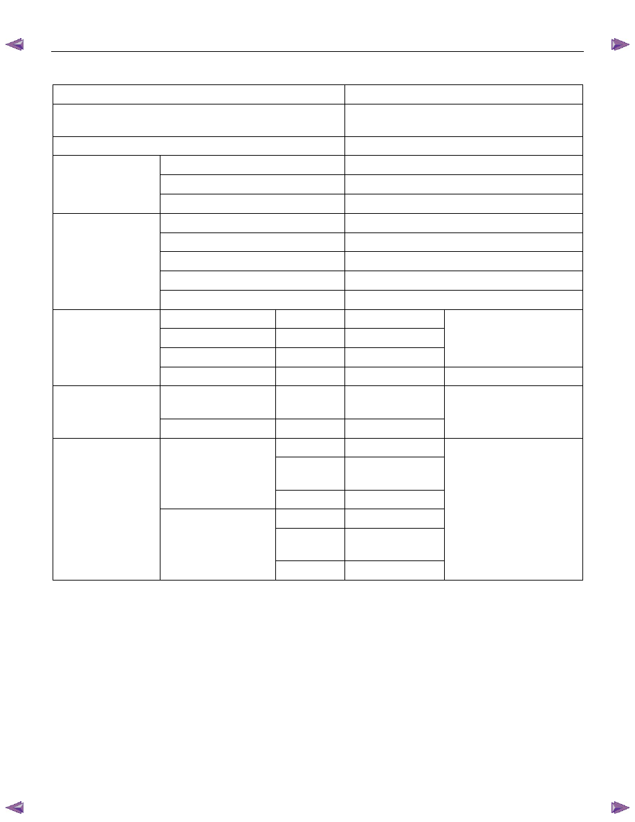
MAIN DATA AND SPECIFICATION
Model
JR405E
Torque Converter Type
Three-Elements, One-Stage & Two-Phases
Type With Lock-up Function
Torque Converter Stall Torque Ratio
1.8
Name
ATF DEXRON III
Quantity
L (US gal/Imp gal)
9.2-9.6 (2.43-2.54/2.02-2.11)
ATF
Cooling System
Water Cooled Type (Radiator)
1st 2.785
2nd 1.545
3rd 1.000
4th (Over Drive)
0.694
Gear Ratio
Reverse 2.272
Low Clutch
L/C
7
High Clutch
H/C
5
Reverse Clutch
R/C
2
Number of Discs
Clutch
Low One-way Clutch
L/O.C
1
Set
Low & Reverse
Brake
L&R/B 6
Brake
2-4 Brake
2-4/B
5
Number of Discs
Sun Gear
33
Pinion
Gear
21
Front Planetary
Ring Gear
75
Sun Gear
42
Pinion
Gear
17
Planetary Gear Unit
Rear Planetary
Ring Gear
75
Number of Teeth
Нет комментариевНе стесняйтесь поделиться с нами вашим ценным мнением.
Текст