Isuzu KB P190. Manual — part 1061
CONSTRUCTION AND FUNCTION 7A1-5
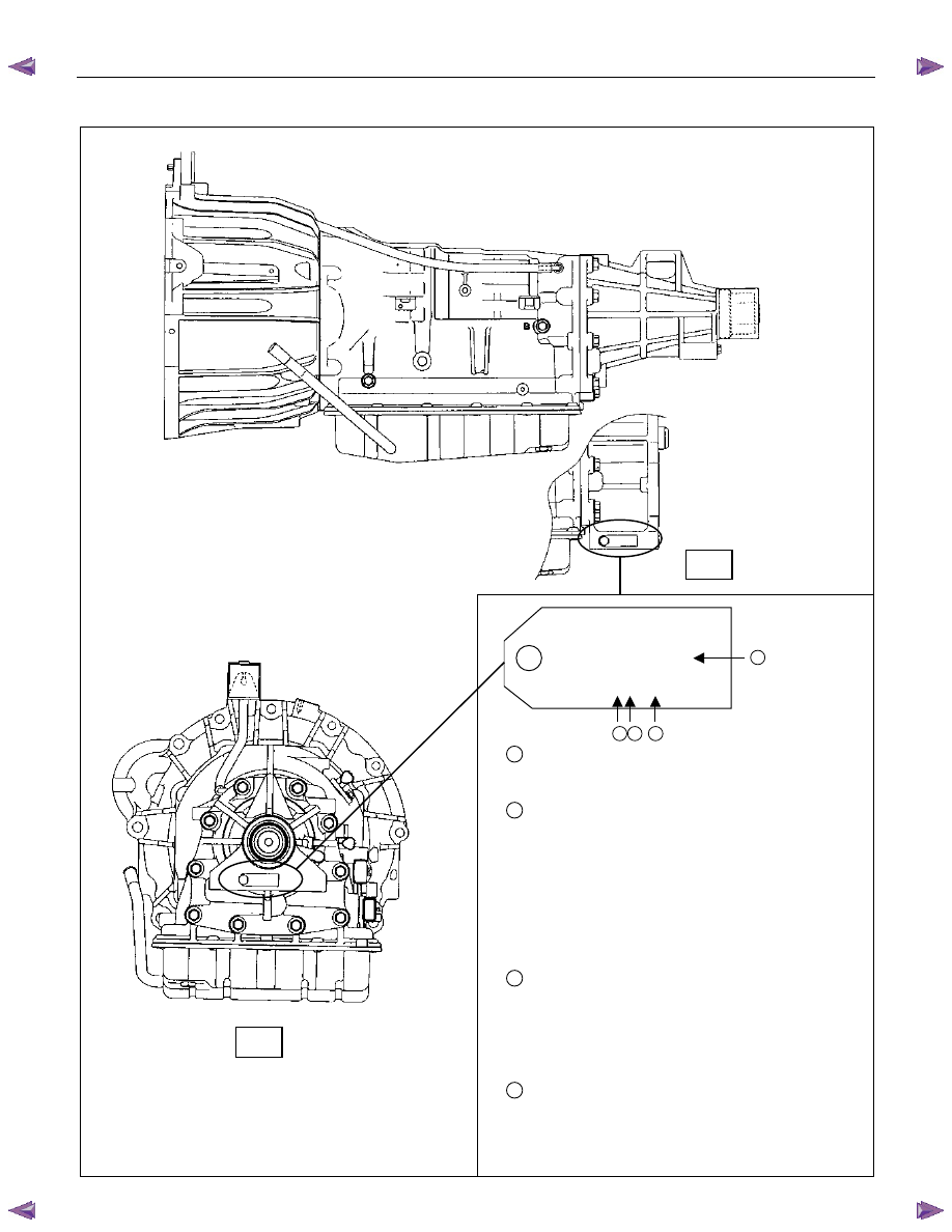
NUMBER PLATE LOCATION
JATCO CORP
UK02
∗∗∗∗
1
No. 1X80652
2 3
4
1
→UK000
UK020 = 2WD
UK021 = 4WD
2
→1
Production Year
1=2001
2=2002
3=2003
4=2004
5=2005
6=2006
7=2007
3
→X
Product Month
1~9=January~September
X=October
Y=November
Z=December
4
→80652
Production Sequence Number
Serial Number Location
2WD:Back of the transmission rear mounting
4WD:Left side of the transmission rear mounting
Figure 2. Number Plate Location
4WD
2WD
7A1-6 CONSTRUCTION AND FUNCTION
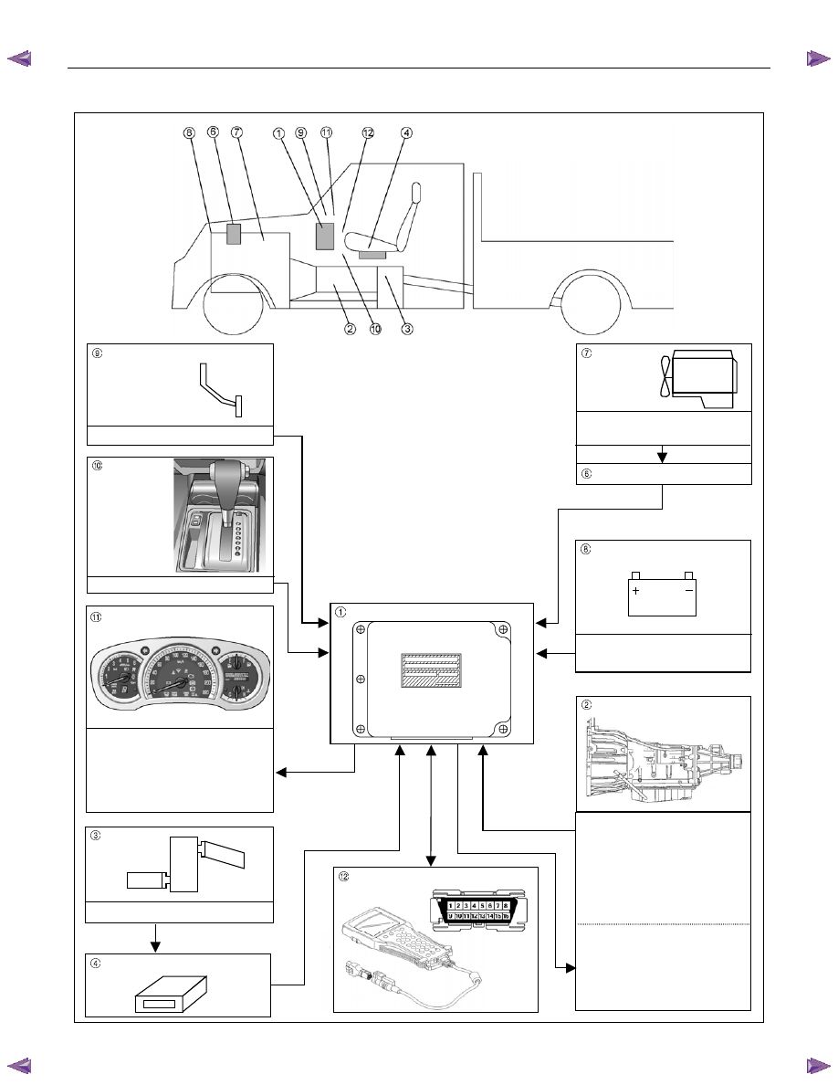
ELECTRONIC CONTROL COMPONENTS LOCATION
4WD Only
4WD Only
Instrument panel (Meter)
Speed meter (2WD Only)
Shift position indicator lamp
POWER DRIVE, 3rd START
indicator lamp
A/T OIL TEMP indicator lamp
CHECK TRANS indicator lamp
Brake pedal
Brake Switch
Transmission Control Module (TCM)
Electrical source
Ignition
Battery voltage
Speed sensor
Turbine sensor
Inhibitor switch
ATF thermo sensor
High clutch oil pressure switch
2-4 brake oil pressure switch
Low & Reverse brake oil pressure
switch
Line pressure solenoid
Low clutch solenoid
High clutch solenoid
2-4 brake solenoid
Low & Reverse brake solenoid
Lock-up solenoid
Transmission
Transfer Control Module
Transfer
4L mode switch
Engine
Engine speed sensor
Accelerator pedal Position Sensor
Engine Control Module (ECM)
Data link connector
Select lever
Power Drive, 3rd Start select switch
Figure 3. Electronic Control Components Location
CONSTRUCTION AND FUNCTION 7A1-7
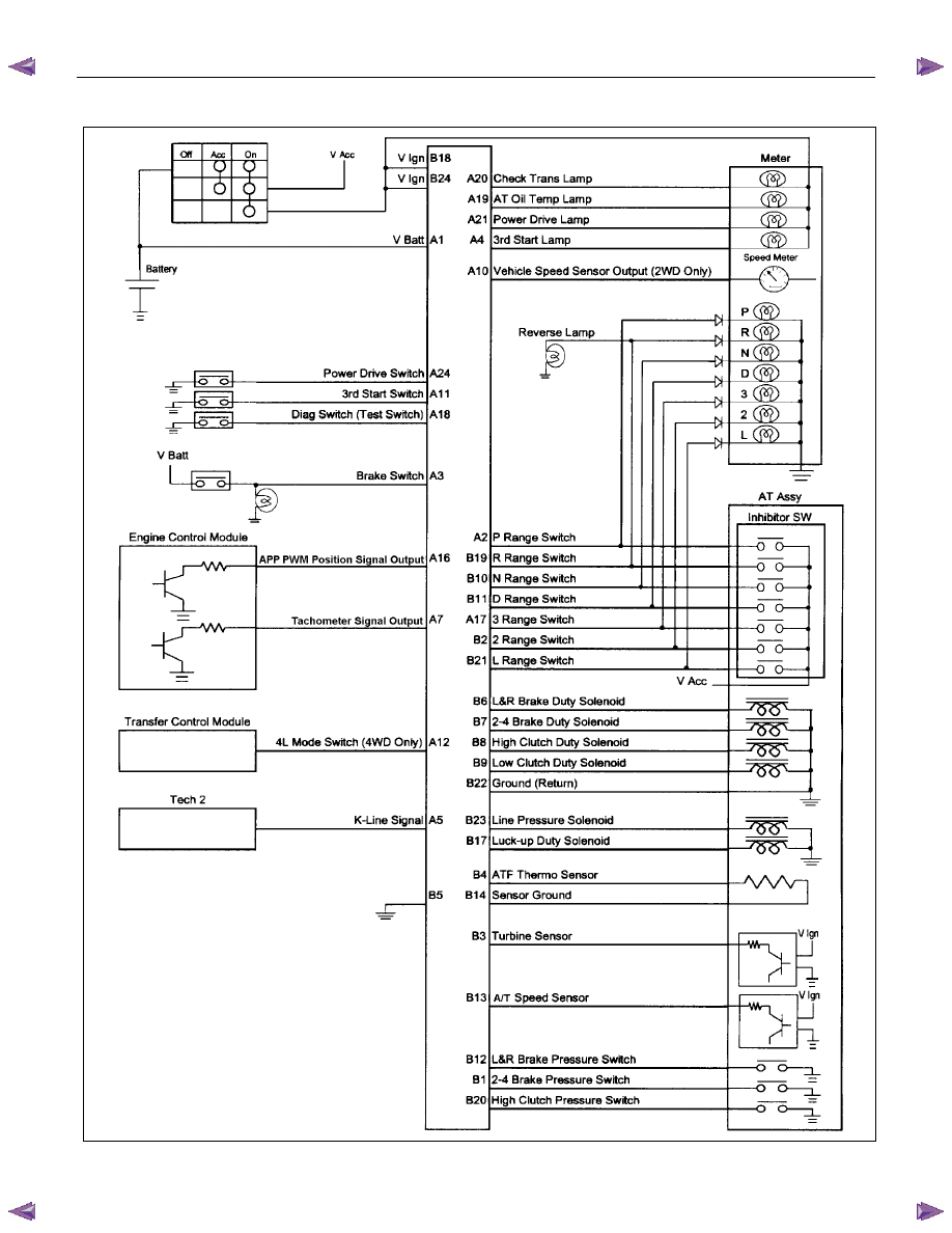
TRANSMISSION CONTROL MODULE (TCM) PERIPHERAL CIRCUIT
Figure 4. TCM Peripheral Circuit
7A1-8 CONSTRUCTION AND FUNCTION
STRUCTURE AND FUNCTION OF COMPONENT
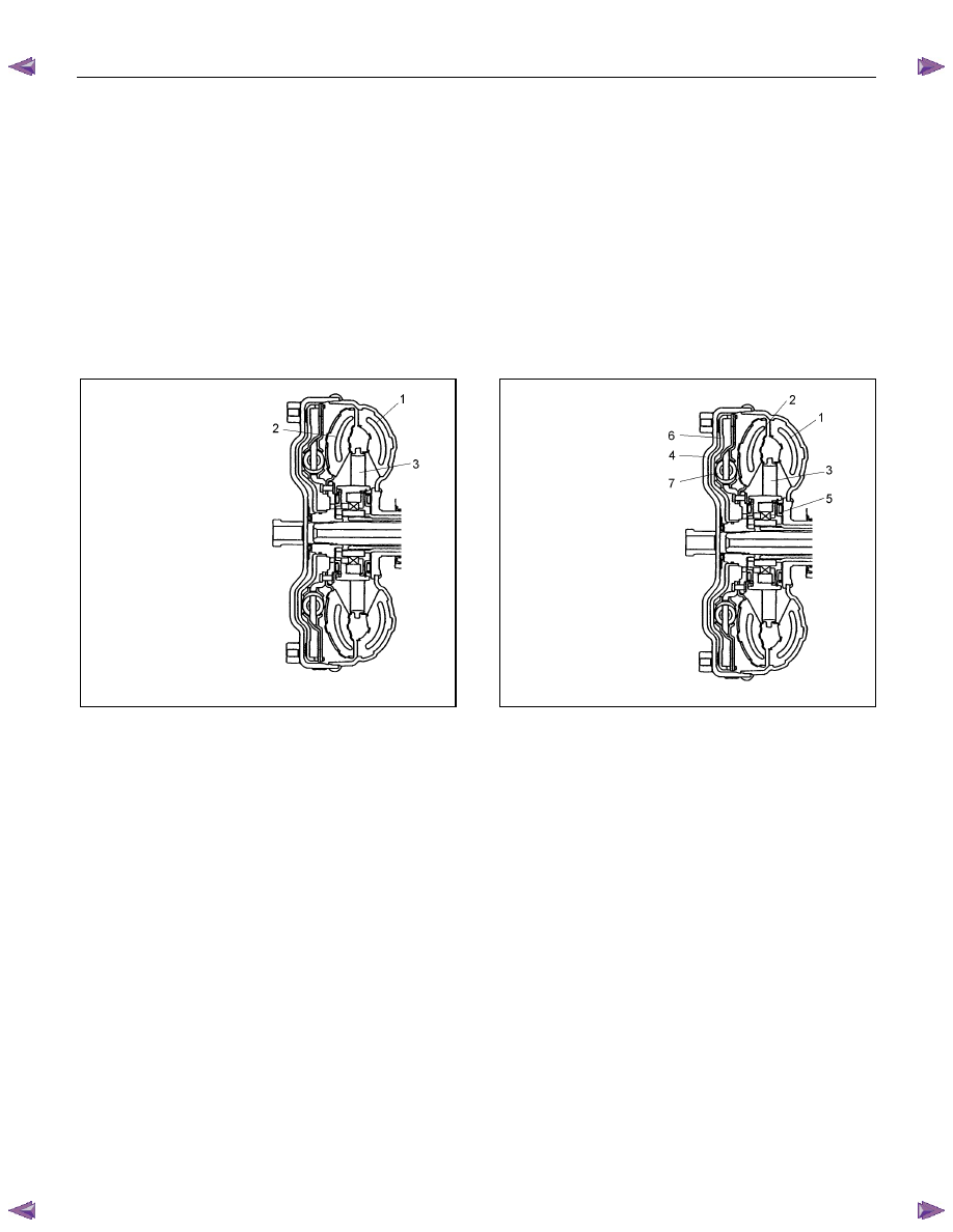
TORQUE CONVERTER (WITH LOCK-UP FUNCTION)
• The torque converter is a device for transmitting the engine torque to the transmission. It transmits power
by means of oil when the lock-up clutch is disengaged, and by means of a lock-up clutch when it is
engaged.
• The torque converter is of the symmetrical, three-element, single-stage, two-phase type.
• As shown in the drawing, the symmetrical three-elements refer to three elements (components) consisting
of impeller (1), turbine (2) and stator (3) that are arranged symmetrically (figure 5).
• "Single-stage" means that there is only one turbine as an output element; "two-phase" means that the
pump impeller acts as a torque converter when the turbine speed is comparatively low, and as a fluid
coupling when the speed is high.
1. Pump Impeller
2. Turbine Runner
3. Stator
1. Pump Impeller
2. Turbine Runner
3. Stator
4. Converter Cover
5. One-way Clutch
6. Lock-up Piston
7. Torsion Damper
Figure 5. Torque Converter
Figure 6. Construction of Torque Converter
Lock-up mechanism
• "Lock-up" refers to a fixed state of the lock-up clutch inside the torque converter and thus connects the
engine directly to the transmission.
• The hydraulic pressure for the lock-up control is supplied from two circuits.
When the lock-up clutch is disengaged (Figure 7)
• When the lock-up is disengaged, the torque converter operating pressure is supplied from the oil passage
(A) to between the cover and the lock-up piston, and separates the lock-up piston clutch facing and
converter cover.
• As a result, the engine drive power is transmitted from the converter cover to the pump impeller, to the
ATF and to the turbine. The torque converter functions as a fluid connector in this condition.
• The torque converter operating pressure is supplied from oil passage (A), and passes through oil passage
(B).
When the lock-up clutch is engaged (Figure 8)
• When the lock-up is engaged, the torque converter operating pressure is supplied from oil passage (B) to
the oil pump impeller, the turbine, and then to the stator side. The oil between the lock-up piston and
converter cover is drained.
• Since the force acting on the right side of the lock-up piston is greater than the force on the left side, it
connects the lock-up piston clutch facing with the converter cover, thereby increasing the transmission
efficiency.
Нет комментариевНе стесняйтесь поделиться с нами вашим ценным мнением.
Текст