Isuzu KB P190. Manual — part 403

6D-24 ENGINE ELECTRICAL (4JK1/4JJ1)
Reassembly
RTW46DLF000601
Reassembly Steps
1. Magnetic Switch Assembly
2. Magnetic
Switch
3. Dust
Cover
4. Plunger
5. Torsion
Spring
6. Shift
Lever
7. Gear
Case
8. Dust
Cover
9. Bolt
10. Pinion Assembly
11. Clutch
12. Pinion Shaft
13. Return Spring
14. Pinion Stopper
15. Pinion Stopper Clip
16. Bearing Retainer
17. Bolt
18. Motor Assembly
19. Armature
20. Yoke
21. Brush Holder
22. Rear Cover
23. Screw
24. Through Bolt
25. Lead Wire
ENGINE ELECTRICAL (4JK1/4JJ1) 6D-25
Important Operations
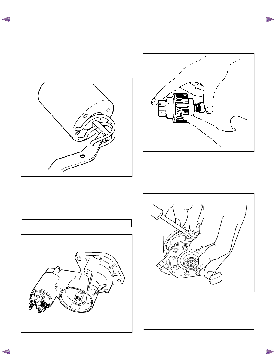
1. Magnetic Switch Assembly
1) Attach the torsion spring to the hole in the
magnetic switch as illustrated.
2) Insert the shift lever into the plunger hole of the
magnetic switch.
RTW46DSH005601
2. Gear Case
3. Dust Cover
1) Install the magnetic switch assembly in the
gear case.
2) Install the dust cover.
Dust Cover Bolt Torque
N
⋅m (kg⋅m/lb in)
8 (0.8 / 69)
RTW46DSH005701
4. Pinion Assembly
Apply a coat of grease to the reduction gear and
install the pinion assembly to the armature shaft.
065RY00041
5. Brush Holders
1) Install the brushes into the brush holder with
raising the spring end of the brush spring.
Take care not to damage the commutator face.
2) Install the brush holder with aligning the
peripheries of the yoke and the brush holder.
RTW46DSH004501
6. Through Bolt
Install the through bolts in the rear cover and
tighten them to the specified torque.
Through Bolt Torque
N
⋅m (kg⋅m/lb in)
8.1 (0.83 / 69.7)
6D-26 ENGINE ELECTRICAL (4JK1/4JJ1)
065RY00044
7. Lead Wire
Connect the lead wire in the magnetic switch and
tighten the terminal nut to the specified torque.
Lead Wire Terminal Nut Torque
N
⋅m (kg⋅m/lb in)
8.6 (0.88 / 74.9)
RTW46DSH002601
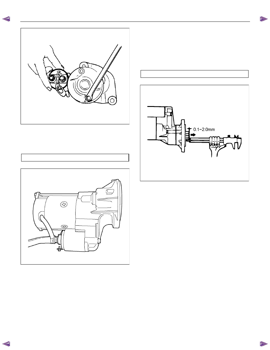
Inspection After Assembly
Use a vernier caliper to measure the pinion shaft thrust
play.
The pinion shaft thrust play is equal to the pinion shaft
end and pinion stopper clearance.
Pinion Shaft Thrust Play
mm (in)
0.1 – 2.0 (0.004 – 0.078)
RTW46DSH005801
ENGINE ELECTRICAL (4JK1/4JJ1) 6D-27
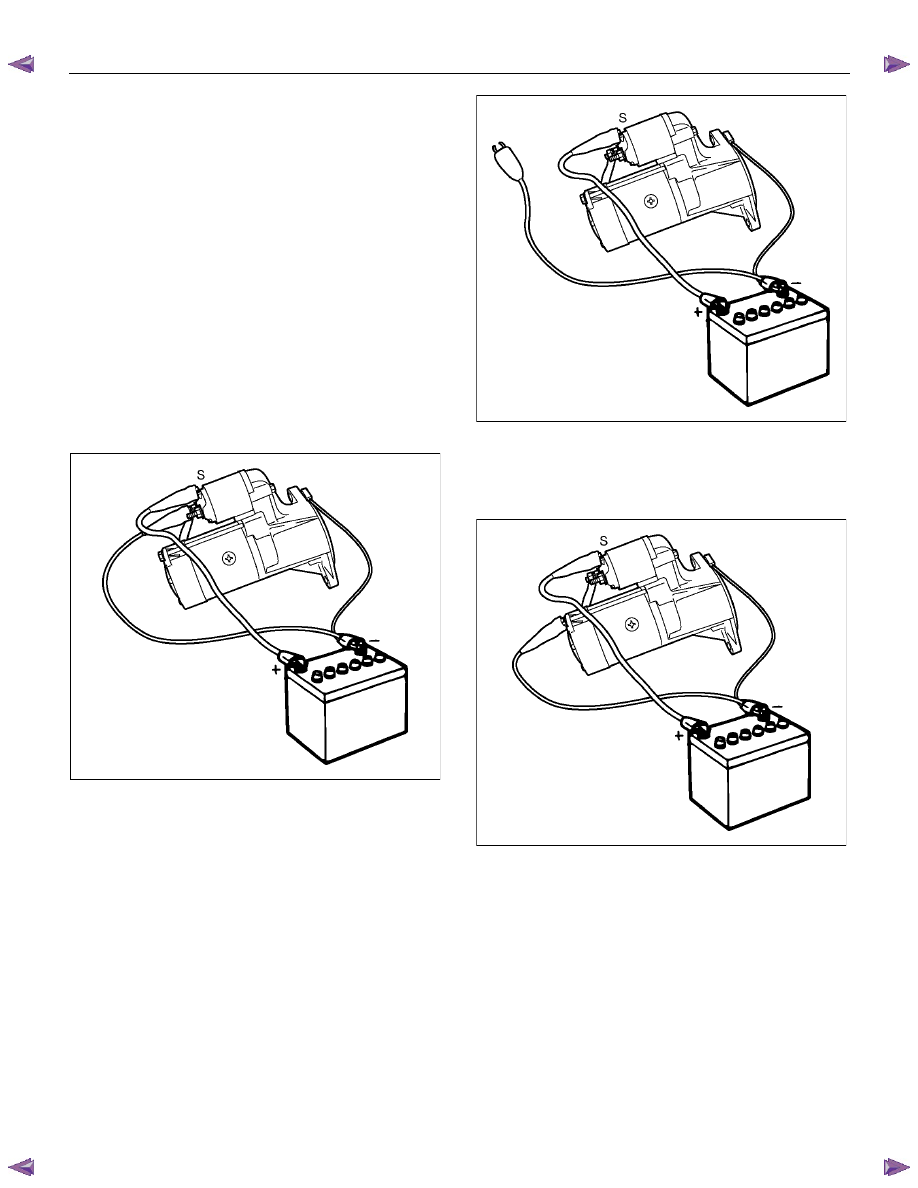
Magnetic Switch
The following tests must be performed with the starter
motor fully assembled.
The yoke lead wire must be disconnected from the “M”
terminal.
To prevent coil burning, complete each test as quickly
as possible (within three to five seconds).
Temporarily connect the solenoid switch between the
clutch and the housing and run the following test.
Complete each test within three to five seconds.
1. Pull-in Test
Connect the battery negative terminal with the
solenoid switch body and the M terminal. When
current is applied to the S terminal from the battery
positive terminal, the pinion should flutter.
RTW46DSH004601
2. Hold-in Maintenance Test
Disconnect the lead at the M terminal. The pinion
should continue to flutter.
RTW46DSH005901
3. Return Test
Disconnect the battery positive lead at the S
terminal.
The pinion should return to its home position.
RTW46DSH004701
Нет комментариевНе стесняйтесь поделиться с нами вашим ценным мнением.
Текст