Isuzu KB P190. Manual — part 800
Engine Cooling – V6 Engine
Page 6B1–65
E n g i n e C o o l i n g F a n
Rotational Speed (with 13
± 0.26 volts negative polarity duty signal applied)
– Stage 1 (25% Duty) . . . . . . 1,100
± 110 rpm
(3
± 0.3A)
– Stage 2 (25% Duty) . . . . . . 1,600
± 160 rpm
(7
± 0.7A)
– Stage 3 (25% Duty) . . . . . . 2,100
± 210 rpm
(15
± 1.5A)
– Stage 4 (25% Duty) . . . . . . 2,400
± 240 rpm
(22
± 2.2A)
Number of Blades . . . . . . . . . . . . . . . . . . . . . . . . . . . . ...5
Fan – Design . . . . . . . . . . . . . . . . . Asymmetrical spaced, curved blades
Material . . . . . . . . . . . . . . . . . . . . ...Nylon Glass, Mineral reinforced
Diameter . . . . . . . . . . . . . . . . . . . . . . . . . . . . . ..500 mm
Fan Motor – Type . . . . . . . . . . . . . . . . . . . . . . . . . . Brushless
Fan Motor – Power . . . . . . . . . . . . . . . . . . . . . . . . . . . 400W
Fan Motor – Input signal . . . . . . . . . . . . . . . . . . . . . . . . 100Hz
Housing . . . . . . . . . . . . . . ..Semi-sealed, zinc-coated steel with drain hole
Direction of Rotation . . . . . . . . . .Counter clockwise (as viewed from drivers seat)
Engine Cooling – V6 Engine
Page 6B1–66
6
Torque Wrench Specifications
N.m
Coolant Outlet housing to Engine Outlet Attaching Bolts. . . . . . . ... 10
Coolant Pump to Front Cover Attaching Bolts . . . . . . . . . . . ... 10
Coolant Pump Pulley Attaching Bolts . . . . . . . . . . . . . . . 12
Coolant Inlet Pipe to Thermostat Housing Attaching Bolt . . . . . . . .. 23
Fan Motor Assembly to Shroud Attaching Screws . . . . . . . . . . .. 5
Heater Pipe Assembly to Thermostat Housing Attaching Bolts . . . . . . 10
Heater Pipe Assembly to Cylinder Head Attaching Bolt . . . . . . . . 35
Thermostat Housing to Engine Block Attaching Bolts. . . . . . . . . 10
Rear Engine Harness . . . . . . . . . . . . . . . . . . . . . 15
Engine Harness Ground Terminal . . . . . . . . . . . . . . . . . 12
Coolant Inlet Pipe To Engine Block Bolt . . . . . . . . . . . . . . 25
Transmission Cooler Lines Bracket . . . . . . . . . . . . . . . .. 23
Engine Cooling – V6 Engine
Page 6B1–67
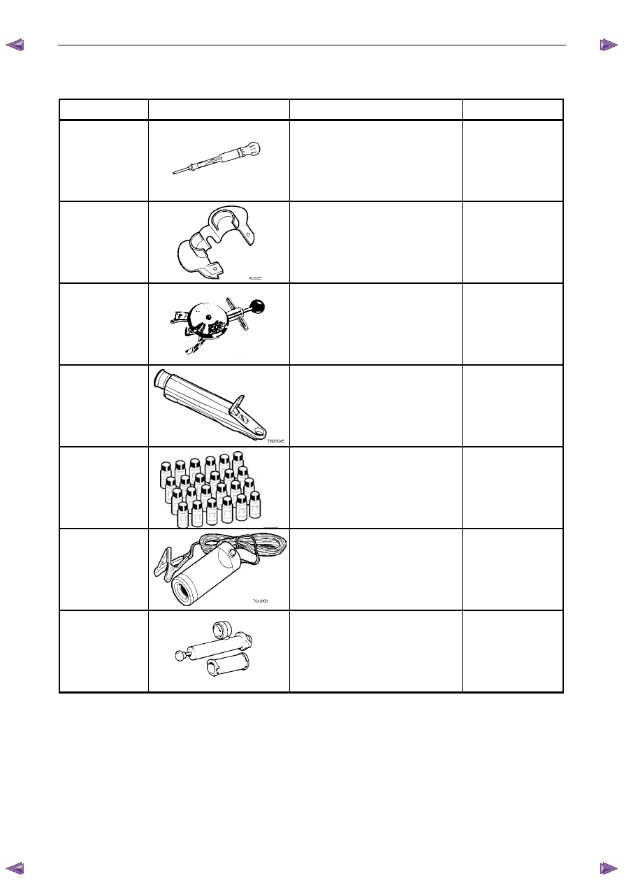
7 Special
Tools
Tool number
Illustration
Description
Classification
AU505
Coolant Tester
Used for testing the coolant
concentration level.
Previously released.
Mandatory
AU525
Quick Connect Release Tool
Used to release the quick connect
fittings on automatic transmission fluid
cooler lines at the radiator end, when
fitted.
Previously released.
Mandatory
BT3373–F
Belt Tension Gauge
Used when checking drive and
accessory belt tension and
adjustments.
Previously released.
Desirable
J 26568
Refractometer
Used for testing coolant concentration
level.
Previously released, as AU 435.
Mandatory
J28431–B
Fluid Dye
Available in 24 x 1-ounce bottles.
Used in conjunction with a black light
such as J42220 to locate the source
of various fluid leaks.
Previously released.
Desirable
J42220
Black Light, Leak Detection Lamp
Used with dye, J28431–B to locate the
source of various vehicle fluid leaks.
Previously released.
Desirable
N/A
Cooling System Pressure Tester
Previously released.
Commercially available.
Mandatory

Fuel System – V6
Page 6C – 1
6C
Fuel System – V6
A T T E N T I O N
Before performing any service operation or other procedure described in this Section, refer to 1.1 WARNING,
CAUTION and NOTES for correct workshop practices with regard to safety and/or property damage.
1
General Information . . . . . . . . . . . . . . . . . . . . . . . . . . . . . . . ...3
Description . . . . . . . . . . . . . . . . . . . . . . . . . . . . . . . . . . . . . . . . 3
Service Precautions. . . . . . . . . . . . . . . . . . . . . . . . . . . . . . . . . . . ... 3
1.1
WARNING, CAUTION and NOTES . . . . . . . . . . . . . . . . . . . . . . . . . . . . . . 4
Definition of WARNING, CAUTION and NOTE Statements. . . . . . . . . . . . . . . . . . . . . 4
WARNING defined . . . . . . . . . . . . . . . . . . . . . . . . . . . . . . . . . . . . 4
CAUTION defined . . . . . . . . . . . . . . . . . . . . . . . . . . . . . . . . . . . .. 4
NOTE defined. . . . . . . . . . . . . . . . . . . . . . . . . . . . . . . . . . . . . . 4
2
System Components. . . . . . . . . . . . . . . . . . . . . . . . . . . . . . . ..5
Fuel System. . . . . . . . . . . . . . . . . . . . . . . . . . . . . . . . . . . . . . . 5
Description . . . . . . . . . . . . . . . . . . . . . . . . . . . . . . . . . . . . . . . 5
Fuel Pump. . . . . . . . . . . . . . . . . . . . . . . . . . . . . . . . . . . . . . . ... 6
Single Turbine Fuel Pump. . . . . . . . . . . . . . . . . . . . . . . . . . . . . . . . .. 6
Fuel Flow . . . . . . . . . . . . . . . . . . . . . . . . . . . . . . . . . . . . . . . . 7
3
System Checks . . . . . . . . . . . . . . . . . . . . . . . . . . . . . . . . . ...8
3.1
Fuel Pump Flow Test . . . . . . . . . . . . . . . . . . . . . . . . . . . . . . . . . . . . 8
3.2
Fuel Pressure Test. . . . . . . . . . . . . . . . . . . . . . . . . . . . . . . . . . . . . 8
Gauge Installation. . . . . . . . . . . . . . . . . . . . . . . . . . . . . . . . . . . . .. 8
Test . . . . . . . . . . . . . . . . . . . . . . . . . . . . . . . . . . . . . . . . . . . 9
Removal . . . . . . . . . . . . . . . . . . . . . . . . . . . . . . . . . . . . . . . . .. 9
3.3
Fuel Leak Test . . . . . . . . . . . . . . . . . . . . . . . . . . . . . . . . . . . . . .. 10
3.4
Fuel System Depressurisation. . . . . . . . . . . . . . . . . . . . . . . . . . . . . . . 11
Repressurise . . . . . . . . . . . . . . . . . . . . . . . . . . . . . . . . . . . . . . 12
4
Service Operations. . . . . . . . . . . . . . . . . . . . . . . . . . . . . . . ...13
4.1
Fuel Lines And Quick Connect Fittings . . . . . . . . . . . . . . . . . . . . . . . . . . . . 13
Description . . . . . . . . . . . . . . . . . . . . . . . . . . . . . . . . . . . . . . ... 13
Leak Test and Inspection . . . . . . . . . . . . . . . . . . . . . . . . . . . . . . . . . 13
Removal . . . . . . . . . . . . . . . . . . . . . . . . . . . . . . . . . . . . . . . . 14
Reinstall . . . . . . . . . . . . . . . . . . . . . . . . . . . . . . . . . . . . . . . . 15
4.2
Fuel Filter. . . . . . . . . . . . . . . . . . . . . . . . . . . . . . . . . . . . . . . .. 15
Removal . . . . . . . . . . . . . . . . . . . . . . . . . . . . . . . . . . . . . . . . 15
Inspection . . . . . . . . . . . . . . . . . . . . . . . . . . . . . . . . . . . . . . . . 16
Reinstallation . . . . . . . . . . . . . . . . . . . . . . . . . . . . . . . . . . . . . ... 16
4.3
Fuel Tank and Pump Assembly . . . . . . . . . . . . . . . . . . . . . . . . . . . . . . .. 17
4.4
Fuel Tank Assembly . . . . . . . . . . . . . . . . . . . . . . . . . . . . . . . . . . . 18
Remove . . . . . . . . . . . . . . . . . . . . . . . . . . . . . . . . . . . . . . . . . 19
Reinstall . . . . . . . . . . . . . . . . . . . . . . . . . . . . . . . . . . . . . . . . 22
4.5
Modular Fuel Pump and Sender Assembly . . . . . . . . . . . . . . . . . . . . . . . . . ... 23
Remove . . . . . . . . . . . . . . . . . . . . . . . . . . . . . . . . . . . . . . . . . 23
Fuel Level Sender Assembly . . . . . . . . . . . . . . . . . . . . . . . . . . . . . . . .. 26
Test . . . . . . . . . . . . . . . . . . . . . . . . . . . . . . . . . . . . . . . . .. 26
Reinstall . . . . . . . . . . . . . . . . . . . . . . . . . . . . . . . . . . . . . . . . 26
Нет комментариевНе стесняйтесь поделиться с нами вашим ценным мнением.
Текст