Isuzu KB P190. Manual — part 193
5D-2 PARKING BRAKE SYSTEM
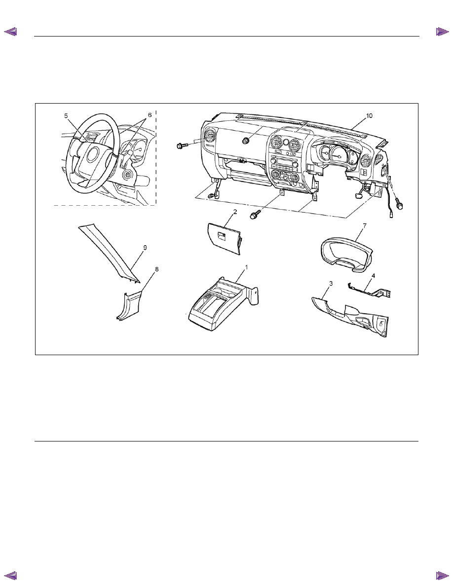
Parking Brake Lever
Parking Brake Lever Assembly and Associated Parts (Bench Seat)
This illustration is based on the RHD model
RTW75DMF000101
Legend
(1) Front Console Assembly
(2) Glove Box
(3) Instrument Panel Driver Lower Cover Assembly
(4) Driver Knee Bolster Assembly
(5) Driver Air Bag
(6) Steering Wheel/Steering Cowl
(7) Meter Cluster Assembly
(8) Dash Side Trim Cover
(9) Front Pillar Trim Cover
(10) Instrument Panel Assembly & Cross Beam
PARKING BRAKE SYSTEM 5D-3
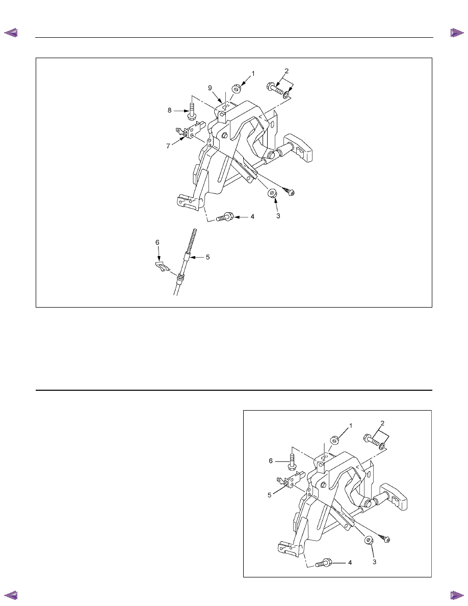
This illustration is based on the RHD model
RTW35DLH000101
Legend
(1) Nut
(2) Bolt and Washer
(3) Adjust Nut
(4) Bolt
(5) Front Parking Brake Cable
(6) Clip
(7) Switch
(8) Bolt
(9) Parking Lever Assembly
Removal
1. Remove instrument panel assembly & cross beam
in legend numbers order.
Refer to section 10.
2. Bolts (2)(6) are already removed in step 1.
3. Remove adjust nut (3).
4. Pull out clip and take out front parking brake cable
from parking lever assembly.
5. Remove bolts (4) and nut (1) and take out parking
lever assembly.
6. Remove switch (5).
RTW65BSH000101
5D-4 PARKING BRAKE SYSTEM
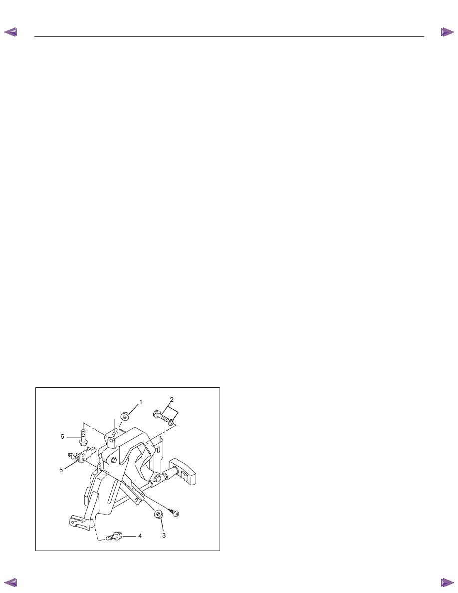
Installation
1. Install switch (5).
Torque: 1.5 N
⋅⋅⋅⋅m (0.15 kgf⋅⋅⋅⋅m/13 lb⋅⋅⋅⋅in)
2. Set parking lever assembly.
3. Install bolts (4) and nut (1) and tighten them to the
specified torque.
Torque: 15 N
⋅⋅⋅⋅m (1.5 kgf⋅⋅⋅⋅m/11 lb⋅⋅⋅⋅ft)
4. Set front parking brake cable in parking lever
assembly.
5. Drive clip into the outer cable groove of front
parking brake cable at the outside of parking lever
assembly.
6. Drive adjust nut (3) on the front end of front
parking brake cable so that front ends of rear
parking brake fit into the rear end (equalizer) of
front cable.
7. Install instrument panel assembly & cross beam.
Refer to section 10.
8. Install bolts (2)(6) and tighten them to the specified
torque.
Torque: 15 N
⋅⋅⋅⋅m (1.5 kgf⋅⋅⋅⋅m/11 lb⋅⋅⋅⋅ft)
9. Install all parts removed.
Refer to section 10.
10. When the parking brake cable is replaced, pull the
parking brake lever with a force equivalent to
operating force: 490 N (50 kg/110 lb), 10 times for
conditioning.
11. Adjust nut (3) so that the lever goes through 8
−14
notches, when pulled with an operation force of
294 N (30 kg/66 lb) and check brake for no drag.
RTW65BSH000101
PARKING BRAKE SYSTEM 5D-5
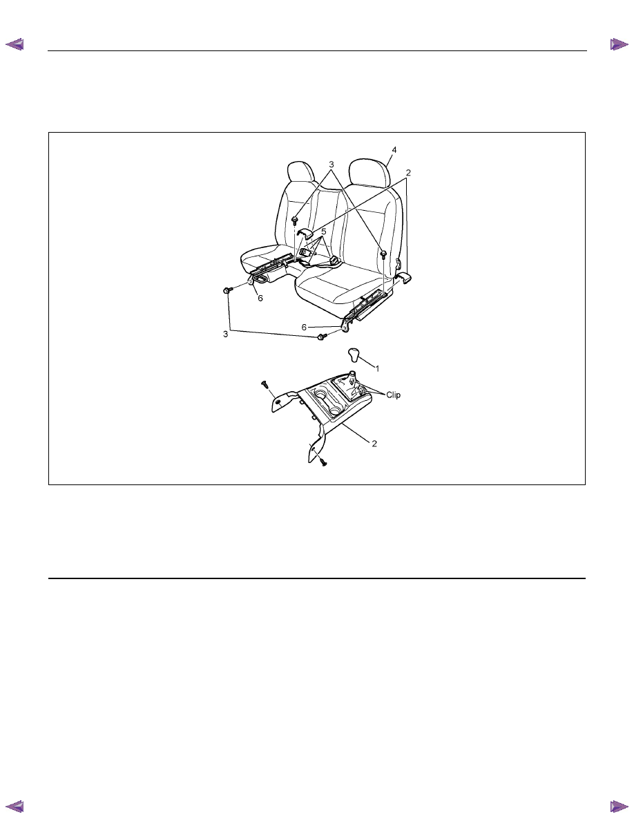
Front Parking Brake Cable
Front Parking Brake Cable and Associated Parts (Bench Seat)
RTW75DMF000301
Legend
(1) Shift Knob (manual transmission)
(2) Front Floor Console
(3) Bolt
(4) Seat Assembly
(5) Buckle: side seat and Center Seat Belt
(6) Seat Adjuster
Нет комментариевНе стесняйтесь поделиться с нами вашим ценным мнением.
Текст