Isuzu KB P190. Manual — part 194
5D-6 PARKING BRAKE SYSTEM
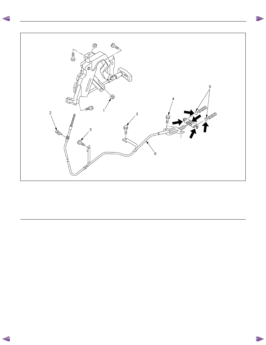
This illustration is based on the RHD model
RTW35DMF000101
Legend
(1) Adjust Nut
(2) Clip
(3) Bolt
(4) Bolt
(5) Parking Brake Cable T-end
(6) Front Parking Brake Cable
Removal
1. Remove seat assembly and seat adjuster.
Refer to section 10.
2. Turn over the carpet so that front parking brake
cable appears.
3. Remove adjust nut.
4. Pull out clip and take out front parking brake cable.
5. Remove bolt.
6. Disconnect parking brake cable T-ends from front
parking brake cable.
7. Take out front parking brake cable through the
floor hole.
Installation
1. Apply grease (multipurpose type grease) to the
connecting portion of parking brake cable T-end
and front parking brake equalizer (arrow mark).
2. Let rear end (equalizer) of front parking brake
cable enter the floor hole and connect it with
parking brake rear cable T-end.
3. Set front parking brake cable in the parking lever
assembly.
4. Drive clip into the outer cable groove of front
parking brake cable at the outside of the parking
lever assembly.
5. Install bolt on the floor and tighten to the specified
torque.
Torque: 15 N
⋅⋅⋅⋅m (1.5 kgf⋅⋅⋅⋅m/11 lb⋅⋅⋅⋅ft)
PARKING BRAKE SYSTEM 5D-7
6. Drive adjust nut on the front end of front parking
brake cable so that parking brake cable T-end fits
into the rear end (equalizer) of front cable.
7. Fit the carpet on the floor.
8. Install seat adjuster and seat assembly.
Refer to section 10.
9. Pull parking brake lever with a force equivalent to
operating force: 490 N (50 kg/110 lb), 10 times for
conditioning.
10.
Adjust nut so that parking brake lever goes
through 8
−14 notches, when pulled with an
operation force of 294 N (30 kg/66 lb).
11. Check brake for no drag.
5D-8 PARKING BRAKE SYSTEM
Parking Brake Lever
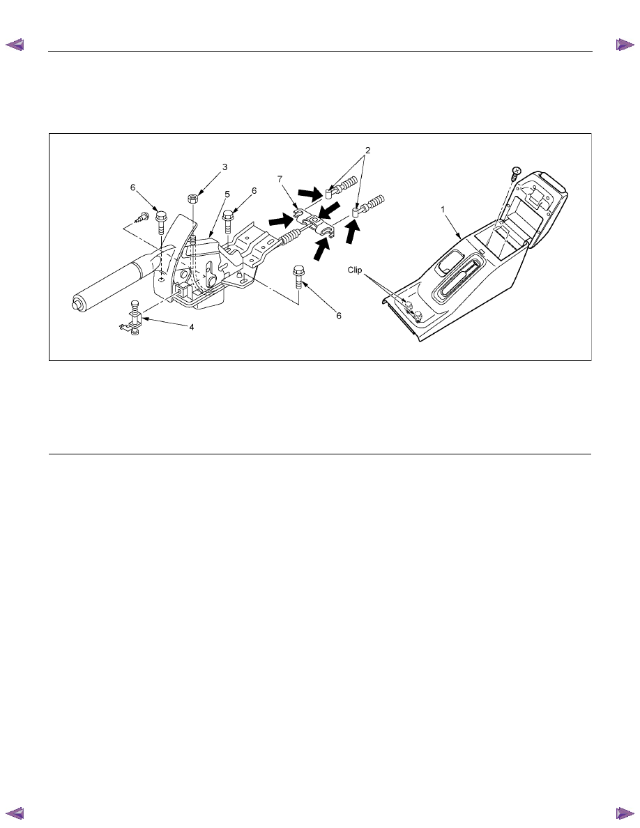
Parking Brake Lever Assembly and Associated Parts (Bucket Seat)
RTW35DSF000101
Legend
(1) Rear Floor Console
(2) Parking Brake Cable T-end
(3) Adjust Nut
(4) Switch
(5) Parking Brake Lever Assembly
(6) Bolt
(7) Equalizer
Removal
1. Remove rear floor console.
Refer to section 10.
2. Loosen adjust nut.
3. Remove bolt.
4. Remove switch.
5. Disconnect parking brake cable T-end from
parking brake lever assembly.
6. Take out parking brake lever assembly.
Installation
1. Apply grease (multipurpose type grease) to the
connecting portion of parking brake rear cable
T-end and parking brake lever equalizer. (arrow
mark).
2. Connect parking brake rear cable T-end to
equalizer.
3. Install switch.
4. Tighten the parking brake lever fixing bolt to the
specified torque.
Torque: 15 N
⋅⋅⋅⋅m (1.5 kgf⋅⋅⋅⋅m/11 lb⋅⋅⋅⋅ft)
5. Drive adjust nut on parking brake assembly so that
parking brake cable T-end fits into equalizer.
6. Install rear floor console.
Refer to section 10.
7. Pull parking brake lever with a force equivalent to
operating force: 490 N (50 kg/110 lb), 10 times for
conditioning.
8. Adjust nut so that parking brake lever goes
through 6
−9 notches, when pulled with an
operation force of 294 N (30 kg/66 lb).
9. Check brake for no drag.
PARKING BRAKE SYSTEM 5D-9
Parking Brake Rear Cable
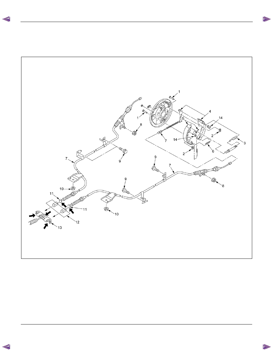
Parking Brake Rear Cable and Associated Parts
RTW55DLF000101
Legend
(1) Tension Pin
(2) Shoe Clamp Spring
(3) Return Spring
(4) Shoe Assembly with Parking Brake Lever
(5) Shoe Assembly with Adjuster Lever
(6) Spring
(7) Parking Brake Rear Cable
(8) Nut
(9) Parking Brake Cable Bolt
(10) Parking Brake Cable Nut
(11) T-end
(12) Outer Cable Retainer
(13) Equalizer
(14) Adjuster Lever Clip
Нет комментариевНе стесняйтесь поделиться с нами вашим ценным мнением.
Текст