Isuzu KB P190. Manual — part 538
6D3-4 STARTING AND CHARGING SYSTEM
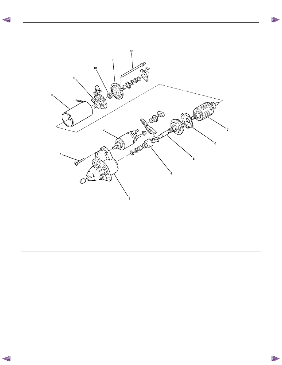
Disassembled View
Legend
1 Bolt
2 Magnetic Switch
3 Gear Case
4 Piston
5 Piston Shaft
6 Center Bracket
7 Armature
8 Yoke Assembly
9 Brush and Brush Holder
10 Washer
11 Rear Cover
12 Through Bolt
STARTING AND CHARGING SYSTEM 6D3-5
Inspection and Repair
Repair or replace necessary parts if extreme wear or damage
is found during inspection.
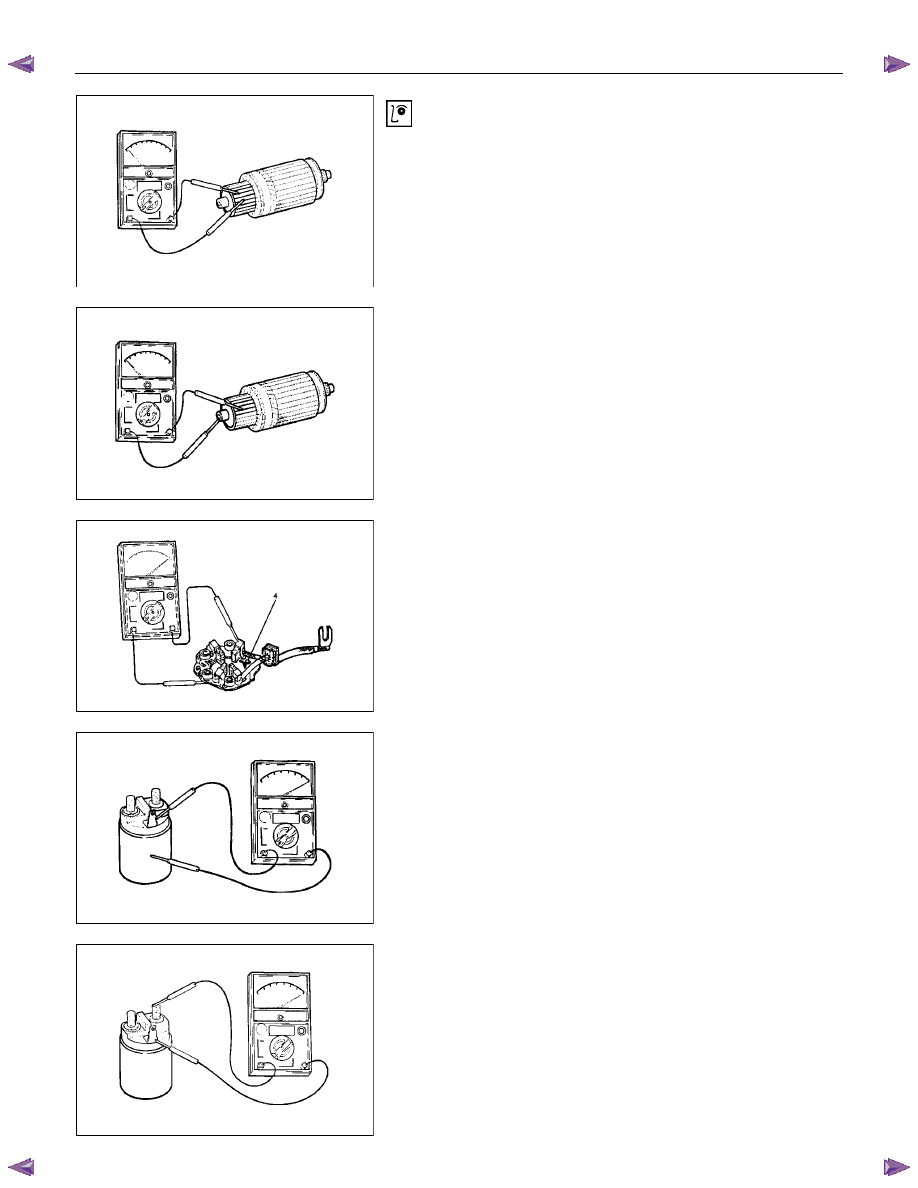
Armature
Check for continuity between commutator and segment.
Replace commutator if there is no continuity (i.e.,
disconnected).
Check for continuity between commutator and shaft.
Also, check for continuity between commutator and armature
core, armature core and shaft. Replace commutator if there is
continuity (i.e., internally grounded).
Brush
Measure the length of brush.
Replace with a new one, if it is below the limit.
Brush Holder
Check for continuity between brush holder (+) (4) and base (-).
Replace, if there is continuity (i.e., insulation is broken).
Magnetic Switch
Check for continuity of shunt coil between terminals S and M.
Replace, if there is no continuity (i.e., coil is disconnected).
Continuity of Series Coil
Check for continuity between terminals S and M.
Replace, if there is no continuity (i.e., coil is disconnected).
6D3-6 STARTING AND CHARGING SYSTEM
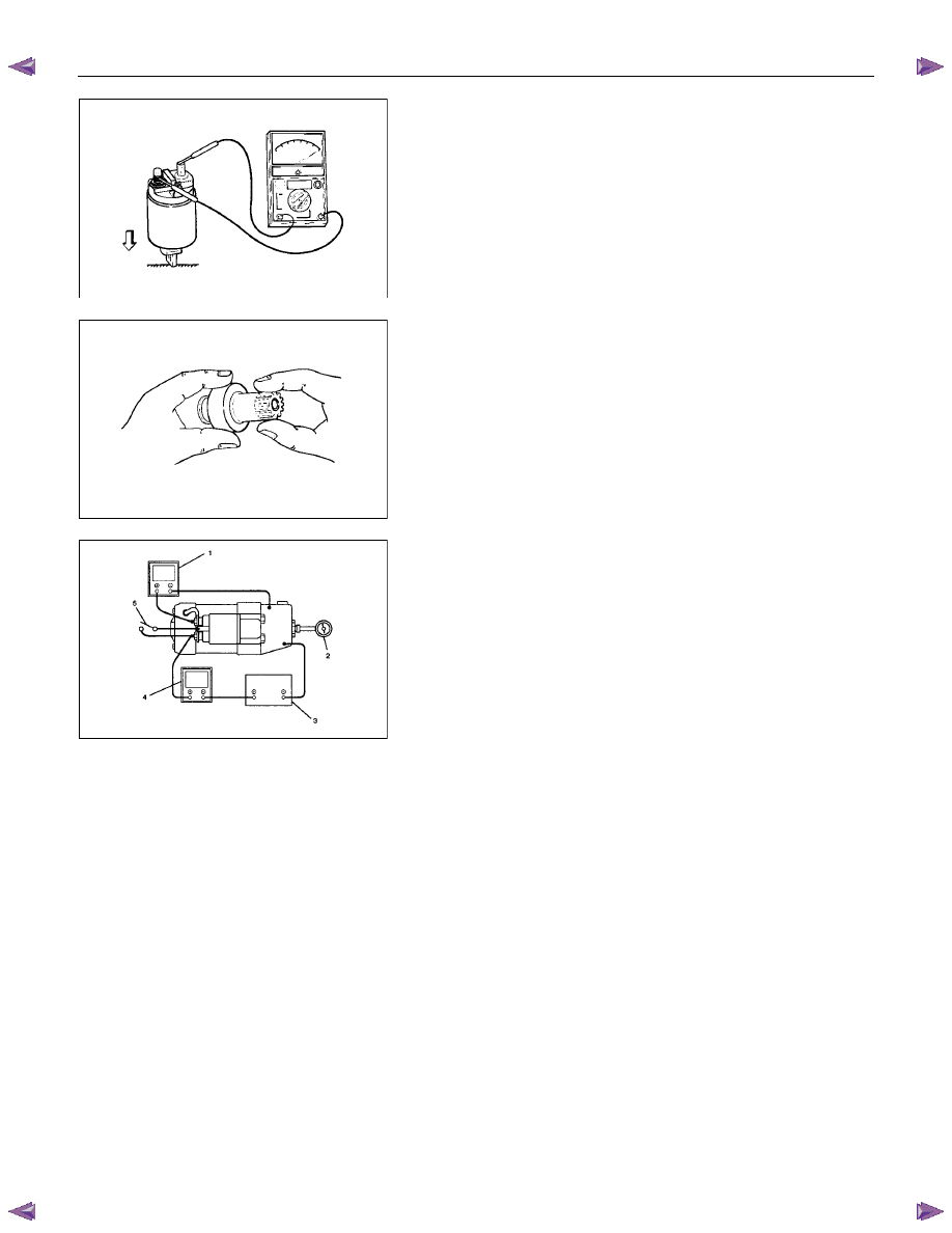
Continuity of Contacts
With the plunger faced downward, push down the magnetic
switch. In this state, check for continuity between terminals B
and M. Replace, if there is no continuity (i.e., contacts are
faulty).
Pinion
Check if the pinion rotates smoothly in drive direction by hand,
or if it is locked when it is rotated in reverse. If not, replace the
pinion.
Characteristic Test
For easily confirming the characteristics, conduct the noload
test as follows:
Rating as short as 30 seconds requires rapid testing.
Fix the starter on the test bench, and wire as shown in
illustration. When the switch is closed, the current flows and
the starter runs under no load. At this time, measure current,
voltage and speed to check if they satisfy the standard.
Legend
1 Volt Meter
2 Revolution Indicator
3 Battery
4 Ammeter
5 Switch
STARTING AND CHARGING SYSTEM 6D3-7
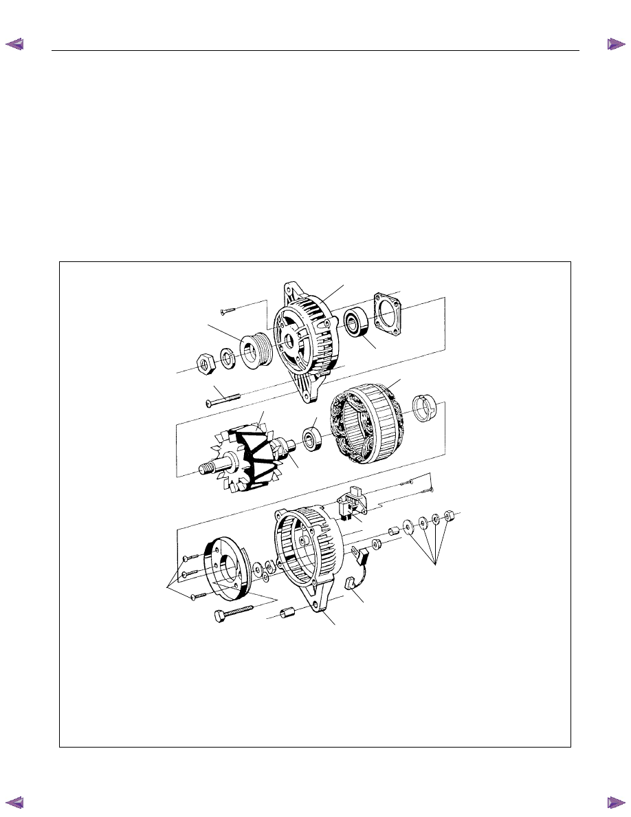
Charging System
General Description
The charging system is an IC integral regulator charging
system and its main components are connected as shown in
illustration.
The regulator is a solid state type and it is mounted along with
the brush holder assembly inside the generator installed on the
rear end cover.
The generator does not require particular maintenance such as
voltage adjustment. The rectifier connected to the stator coil
has eight diodes to transform AC voltage into DC voltage.
This DC voltage is connected to the output terminal of
generator.
Legend
1 Startor assembly
2 Housing
3 Slipring
4 Screws (2)
5 Regulator
6.Bolt (4)
7 Rectifier assembly
8 Retaining assembly
9 B+ terminal nut and washer
10 Pulley
11 Rotor assembly
12 Ball bearing
2
11
12
2
8
5
4
3
1
11
7
6
10
9
Нет комментариевНе стесняйтесь поделиться с нами вашим ценным мнением.
Текст