Isuzu KB P190. Manual — part 537
IGNITION SYSTEM 6D2-5
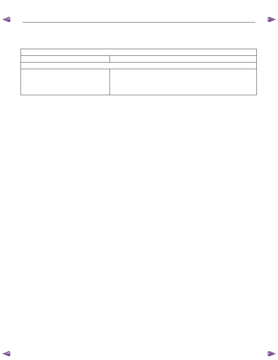
Main Data and Specifications
General Specifications
Ignition System
Ignition Form
Electronic Ignition System (El system) with Crankshaft angle Sensor
Spark Plug
Type
No. of Coils and Type
Coil Location
Torque
Electronic Spark Control
2 Solid State
Engine-mounted
20 N
⋅m (2.0 kgf⋅m)
SECTION 6D3
STARTING AND CHARGING SYSTEM
TABLE OF CONTENTS
PAGE
Starting System . . . . . . . . . . . . . . . . . . . . . . . . . . . .. 6D3- 2
General Description . . . . . . . . . . . . . . . . . . . . . . . . . ... 6D3- 2
Service Precaution . . . . . . . . . . . . . . . . . . . . . . . . . . . 6D3- 2
Diagnosis . . . . . . . . . . . . . . . . . . . . . . . . . . . . . . 6D3- 2
Starter. . . . . . . . . . . . . . . . . . . . . . . . . . . . . . . .. 6D3- 3
Removal . . . . . . . . . . . . . . . . . . . . . . . . . . . . . .. 6D3- 3
Installation. . . . . . . . . . . . . . . . . . . . . . . . . . . . .. 6D3- 3
Disassembled View . . . . . . . . . . . . . . . . . . . . . . . . ... 6D3- 4
Inspection and Repair . . . . . . . . . . . . . . . . . . . . . . . ... 6D3- 5
Characteristic Test . . . . . . . . . . . . . . . . . . . . . . . . . 6D3- 6
Charging System . . . . . . . . . . . . . . . . . . . . . . . . . . . 6D3- 7
General Description . . . . . . . . . . . . . . . . . . . . . . . . . ... 6D3- 7
General On-Vehicle Inspection . . . . . . . . . . . . . . . . . . . . . . 6D3- 8
Generator . . . . . . . . . . . . . . . . . . . . . . . . . . . . . . 6D3- 8
Removal . . . . . . . . . . . . . . . . . . . . . . . . . . . . . .. 6D3- 8
Inspection. . . . . . . . . . . . . . . . . . . . . . . . . . . . ... 6D3- 8
Installation. . . . . . . . . . . . . . . . . . . . . . . . . . . . .. 6D3- 9
Diagnosis . . . . . . . . . . . . . . . . . . . . . . . . . . . . . . 6D3-12
Disassembly. . . . . . . . . . . . . . . . . . . . . . . . . . . ... 6D3-13
Clean . . . . . . . . . . . . . . . . . . . . . . . . . . . . . . ... 6D3-14
Inspection. . . . . . . . . . . . . . . . . . . . . . . . . . . . ... 6D3-14
Reassembly. . . . . . . . . . . . . . . . . . . . . . . . . . . . 6D3-18
Inspection. . . . . . . . . . . . . . . . . . . . . . . . . . . . ... 6D3-19
Technical Data . . . . . . . . . . . . . . . . . . . . . . . . . . . . 6D3-21
STARTING AND CHARGING SYSTEM 6D3-1
6D3-2 STARTING AND CHARGING SYSTEM
Starting System
General Description
Cranking Circuit
The cranking system consists of a battery, starter, starter
switch, starter relay, etc. These main components are
connected.
Starter
The cranking system employs a magnetic type reduction
starter in which the motor shaft is also used as a pinion shaft.
When the starter switch is turned on, the contacts of magnetic
switch are closed, and the armature rotates. At the same time,
the plunger is attracted, and the pinion is pushed forward by
the shift lever to mesh with the ring gear.
Then, the ring gear runs to start the engine. When the engine
starts and the starter switch is turned off, the plunger returns,
the pinion is disengaged from the ring gear, and the armature
stops rotation. When the engine speed is higher than the
pinion, the pinion idles, so that the armature is not driven.
Service Precaution
CAUTION:
Always use the correct fastener in the proper location.
When you replace a fastener, use ONLY the exact part
number for that application. ISUZU will call out those
fasteners that require a replacement after removal. ISUZU
will also call out the fasteners that require thread lockers
or thread sealant. UNLESS OTHERWISE SPECIFIED, do
not use supplemental coatings (Paints, greases, or other
corrosion inhibitors) on threaded fasteners or fastener
joint interfaces. Generally, such coatings adversely affect
the fastener torque and the joint clamping force, and may
damage the fastener. When you install fasteners, use the
correct tightening sequence and specifications. Following
these instructions can help you avoid damage to parts
and systems.
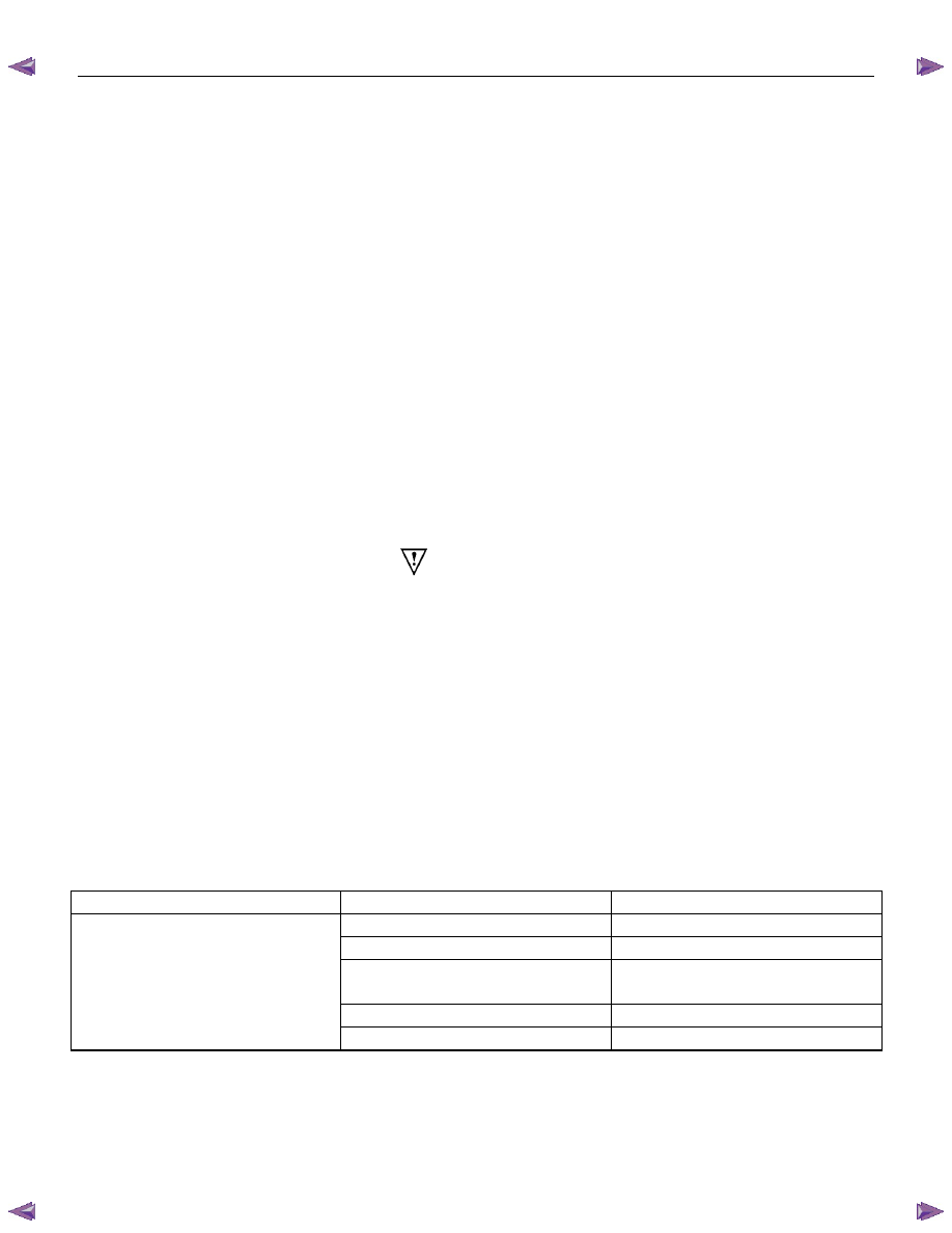
Diagnosis
Condition Possible
cause Correction
Starter does not run
Charging failure
Repair charging system
Battery Failure
Replace Battery
Terminal connection failure
Repair or replace terminal connector
and/or wiring harness
Starter switch failure
Repair or replace starter switch
Starter failure
Repair or replace starter

STARTING AND CHARGING SYSTEM 6D3-3
Starter
Removal
1. Remove the battery ground cable.
2. Remove harness connectors (1) and (2).
3. Remove bolts from starter.
Installation
1. Install starter assembly.
2. Install mounting bolts and tighten bolts to specified torque.
Torque: 51 N
⋅⋅⋅⋅m (5.2 kgf⋅⋅⋅⋅m)
3. Connect harness.
4. Reconnect the battery ground cable.
Нет комментариевНе стесняйтесь поделиться с нами вашим ценным мнением.
Текст