Isuzu KB P190. Manual — part 633

Engine Mechanical – V6
Page 6A1–53
3
Minor Service Operations
A T T E N T I O N
The V6 engine is a combination of numerous components, containing machined, honed, polished and lapped
surfaces manufactured on the latest, high technology production equipment. Many of the components
contain tolerances measured in thousandths of a millimetre. Consequently, when any engine component is to
be serviced, care and cleanliness are extremely important.
Prior to re-assembly of the engine, all components must be cleaned and inspected in accordance with the
relevant clean and inspect procedures throughout this Section, and replaced or repaired where required.
In addition to cleaning and inspecting components, a liberal coating of engine oil should be applied to friction
surfaces during assembly to protect and lubricate the surfaces on initial operation.
When performing any service operation, it should be understood that correct cleaning and protection of
machined surfaces and friction areas is part of the repair procedure. This is considered standard workshop
practice, even if not specifically stated. Torque values must be used as specified during reassembly to
ensure correct retention of all components.
Through out this section, fastener torque wrench specifications may be accompanied with the following
identification marks:
■
Fasteners must be replaced after loosening.
Fasteners either have micro encapsulated sealant applied or incorporate a mechanical thread lock and
should only be re-used once. If in doubt, replacement is recommended.
If one of these identification marks is present alongside a fastener torque wrench specification, the
recommendation regarding that fastener must be adhered to.
Engine Mechanical – V6
Page 6A1–54
3.1 Engine
Oil
The procedure outlined below is typically the same for both rear wheel drive and all wheel drive vehicles.
Check
The following procedure is applicable to both rear wheel and all wheel drive vehicles
1
Run the engine to bring it to normal operating temperature.
2
Park the vehicle on a level surface. A vehicle that is not level will affect the accuracy of the level reading.
3
Stop the engine and wait 5 to 10 minutes to allow the oil to drain back into the oil pan.
4
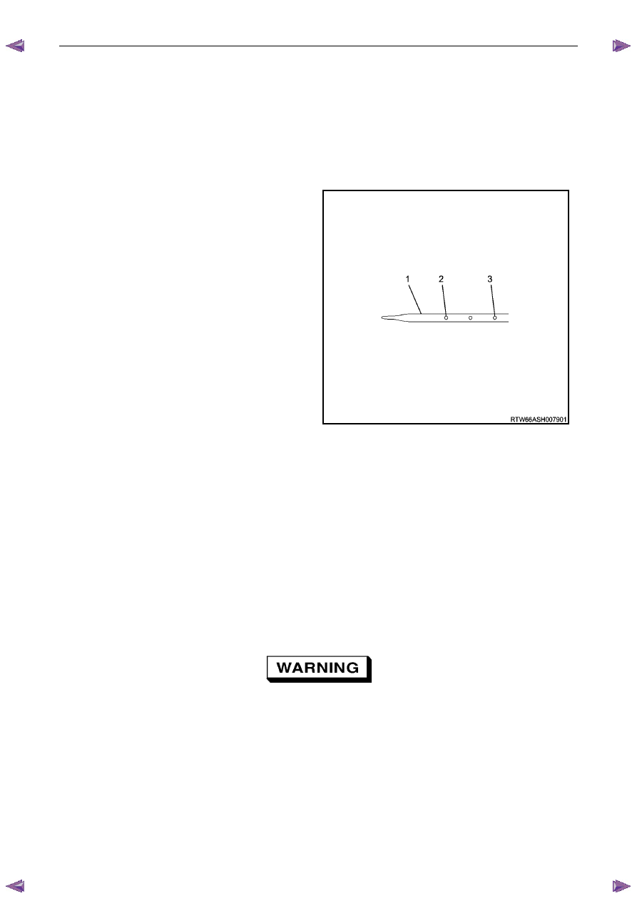
Remove the oil level indicator (1) and wipe clean.
5
Insert the indicator, ensuring it is fully seated.
6
Slowly remove the indicator to avoid smearing. Hold it
horizontally or with lower end slightly down to avoid
oil running along indicator.
7
Observe the oil level where it passes over the centre
line of the indicator.
8
If the level is lower than the Add mark (2), add
enough oil to the engine to reach the Upper mark (3).
Do not add too much oil as the reading should never
be above the Upper mark.
N O T E
When topping up the oil, allow approximately 5
to 10 minutes for the added oil to fully drain into
the oil pan.
Figure 6A1 – 23
Replace
N O T E
• Quicker and more complete draining will
occur if the engine oil is at normal operating
temperature. However, care must be taken to
avoid scalding from the hot oil.
• It recommended the oil filter be changed at
each engine oil change, refer to 3.2
Oil
Filter.
1
Remove the oil fill cap.
2
To ensure complete draining of the oil pan, raise the front and rear of the vehicle to maintain a level attitude. If not
using a hoist, support the vehicle with safety stands, refer to 0A General Information.
3
Clean any foreign material from around the oil drain plug and place a suitable, clean drain tray under the engine.
The oil may be hot. Avoid contact with the oil.
Ensure that eyes and skin are protected.
4
Remove the drain plug (1), taking care to avoid scalding from the hot oil. Allow the oil to drain.
5
Clean and inspect the drain plug threads. If damaged, replace the drain plug.
Engine Mechanical – V6
Page 6A1–55
Figure 6A1 – 24
6
Once the oil has completely drained, reinstall the drain plug and tighten to the correct torque specification.
Oil pan drain plug
torque specification . . . . . . . . . . . 25.0 Nm
7
Replace the oil filter, refer to 3.2
Oil Filter.
8
Lower the vehicle to the ground and fill with the specified amount of SAE 5W30 lubricant.
Engine Oil Capacity:
With Oil Filter Change. . . . . . . . . . 6.5 litres
9
Install the oil fill cap.
10
Start the engine and check for leaks.
Pressure Check
1
Run the engine to bring it to normal operating temperature.
2
Park the vehicle on a level surface. A vehicle not level will affect the accuracy of the level reading.
3
Stop the engine and wait 5 to 10 minutes to allow the oil to drain back into the oil pan.
4
Check the oil level and top up with the recommended engine oil as required, refer to Check, in this Section.
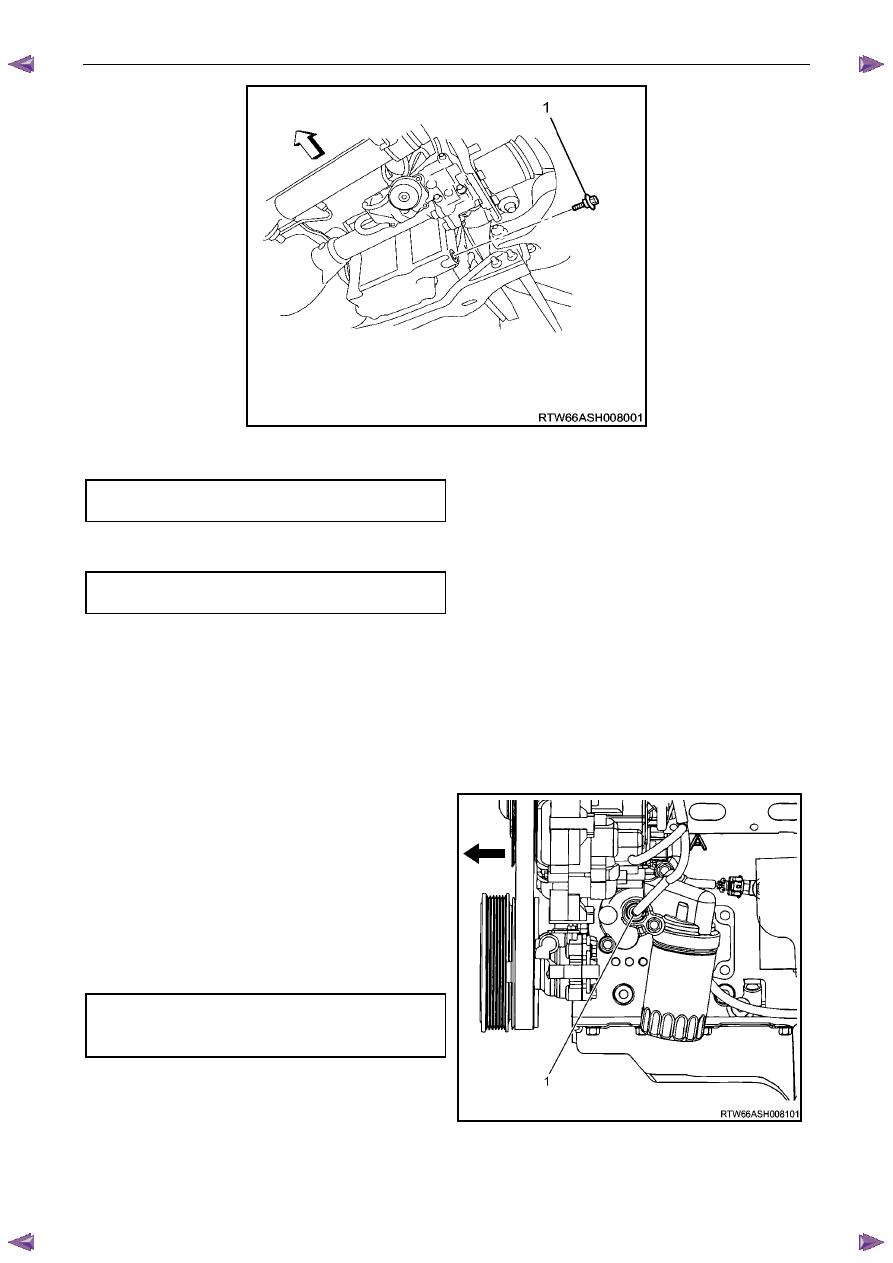
5
Remove the engine oil pressure sensor (1), refer to
6C1-3 Engine Management – V6 – Service
Operations.
6
Install the oil pressure gauge adaptor, Tool No.
J36648-A into the oil pressure sender hole in the oil
filter housing.
7
Install a suitable oil pressure gauge into the adaptor.
8
Start the engine.
9
Measure and record the pressure reading on the
gauge at idle and 2000 r.p.m. Compare the results
with the specification.
Minimum engine oil pressure
@ idle. . . . . . . . . . . . . . . . ... 69 kPa
@ 2000 r.p.m. . . . . . . . . . . . . . 138 kPa
10
If the engine oil pressure is not to specification, refer to
2.19
Engine Oil Pressure Diagnosis.
11
After completing the engine oil pressure check, stop
the engine and remove the oil pressure gauge.
Figure 6A1 – 25
12
Reinstall the oil pressure sensor, refer to 6C1-3 Engine Management – V6 – Service Operations.
13
Start the engine and check for leaks.
Engine Mechanical – V6
Page 6A1–56
3.2
Oil Filter Cartridge
Replace
N O T E
• The oil filter cartridge should be replaced at
the correct time or distance intervals, refer to
0B Lubrication and Service.
• The oil filter cartridge should also be replaced
whenever the engine oil is suspected to have
been contaminated by foreign material.
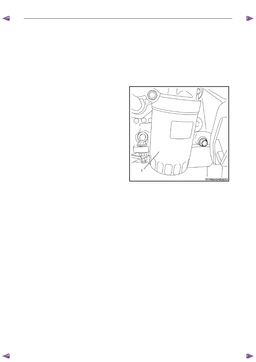
1
Remove and discard the oil filter cartridge (1).
2
Install the new oil filter cartridge.
Figure 6A1 – 26
Нет комментариевНе стесняйтесь поделиться с нами вашим ценным мнением.
Текст