Isuzu KB P190. Manual — part 634
Engine Mechanical – V6
Page 6A1–57
3.3
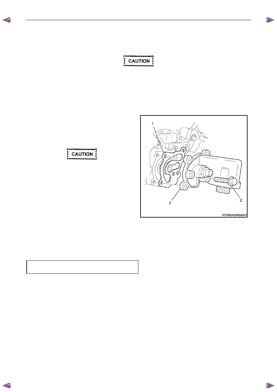
Oil Filter Adaptor
Remove
Disconnection of the battery affects certain
vehicle electronic systems, refer to 1.1
WARNING, CAUTION and NOTES before
disconnecting the battery.
1
Disconnect the battery negative terminal.
2
Disconnect the wiring harness connector from the oil pressure sender.
3
Remove the oil filter adaptor attaching bolts (2), four
places.
4
Remove the oil filter adaptor and discard the gasket
(3).
5
Clean the surfaces of the adaptor and cylinder block.
• Do not use a screwdriver or similar to
prise the oil filter adapter from the engine
as damage to the sealing surface may
occur.
• If required, use a rubber mallet to tap the
oil filter adapter to loosen the
components prior to separating.
Tapping should be done at bends,
corners or reinforced areas to prevent
distortion of parts.
Figure 6A1 – 27
Reinstall
Reinstallation of the oil filter adaptor is the reverse of the removal procedure, noting the following:
1
A new gasket must be used.
2
Loosely install the oil filter adaptor attaching bolts, then tighten all fasteners to the correct torque specification.
Oil filter adaptor attaching bolt
torque specification . . . . . . . . .. 20.0- 26.0 Nm
Engine Mechanical – V6
Page 6A1–58
3.4
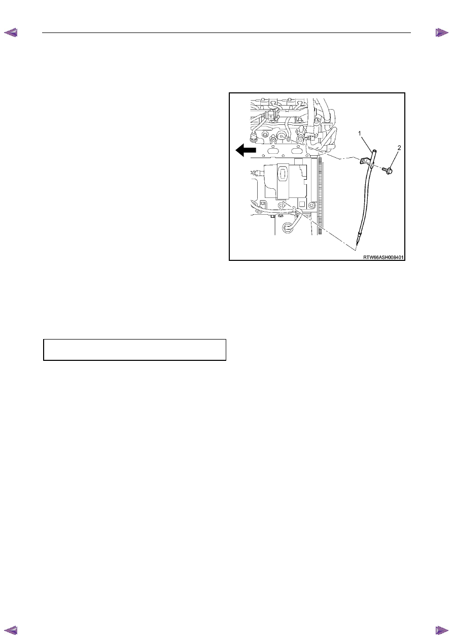
Oil Level Indicator Tube
Remove
1
Remove the oil level indicator from the oil level indicator tube.
2
Remove the bolt (2) attaching the oil level indicator
tube (1) and engine wiring harness retaining bracket.
3
Withdraw the oil level indicator tube from the oil pan.
4
Remove and discard the o-ring at the bottom of the oil
level indicator tube.
Figure 6A1 – 28
Reinstall
Reinstallation of the oil level indicator tube is the reverse of the removal procedure, noting the following:
1
Install a new oil level indicator o-ring.
2
Ensure the attaching bolt passes through the engine wiring harness retaining bracket.
3
Tighten bolt to the correct torque specification.
Oil level indicator tube attaching bolt
torque specification . . . . . . . . ...8.0 – 12.0 Nm
Engine Mechanical – V6
Page 6A1–59
3.5
Accessory Drive Belt
RWD Vehicle
Remove
1
Remove the air intake duct from between the air flow meter and the throttle body, refer to 6C1-3 Engine
Management – V6 – Service Operations.
2
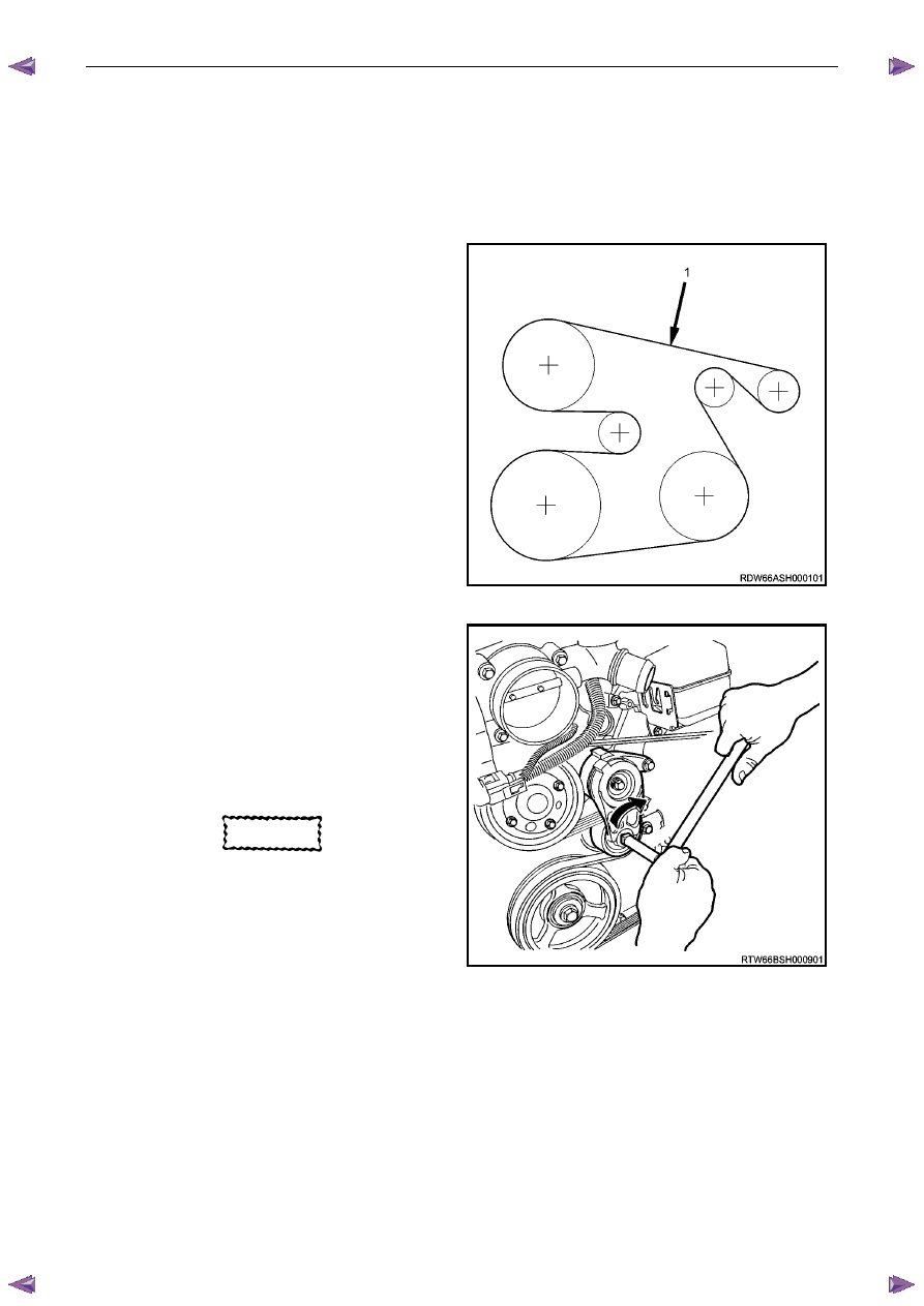
Note the accessory drive belt (1) routing.
Figure 6A1 – 29
3
Using a suitable ½” drive socket bar (1), rotate the
drive belt tensioner (2) clockwise, to reduce belt
tension.
4
While holding the tensioner in the reduced tension
position, remove the accessory drive belt (3).
N O T E
If required use an assistant to maintain the
tensioner in the required position.
CAUTION
If running the engine with the accessory
drive belt removed, the coolant pump will
not be operating and the engine may
overheat if left unsupervised even for a short
period.
Figure 6A1 – 30
Reinstall
1
Install the drive belt over the A/C compressor, idler pulley, power steering pump, coolant pump, generator and
tensioner pulleys.
2
Using a suitable ½” drive socket bar (1), rotate the drive belt tensioner (2) clockwise, refer to Figure 6A1 – 30.
3
With an assistant holding the tensioner in the required position, feed the accessory drive belt (3) over the
crankshaft pulley.
4
Slowly release the drive belt tensioner mechanism.
Engine Mechanical – V6
Page 6A1–60
N O T E
Ensure the drive belt ribs are correctly aligned
with the grooves in the accessory drive pulleys or
damage to the drive belt and accessory drive
components and pulleys may occur.
5
Reinstall the air intake duct to the air flow meter and the throttle body, refer to 6C1-3 Engine Management – V6 –
Service Operations.
6
Run the engine to ensure correct operation.
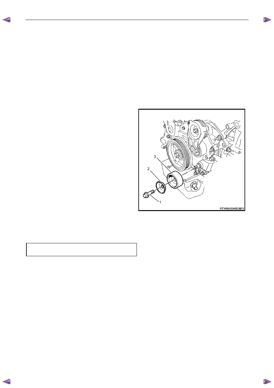
3.6
Accessory Drive Belt Idler Pulley
Remove
1
Remove the accessory drive belt, refer to 3.5
Accessory Drive Belt.
2
Remove the accessory drive belt idler pulley attaching
bolt (1).
3
Remove the dished washer (2) and accessory drive
belt idler pulley (3).
Figure 6A1 – 31
Reinstall
Reinstallation of the accessory drive belt idler pulley is the reverse of the removal procedure. Tighten the bolt to the
correct torque specification.
Accessory drive belt idler pulley
attaching bolt torque specification. . . . . ..50.0 Nm
Нет комментариевНе стесняйтесь поделиться с нами вашим ценным мнением.
Текст