Isuzu KB P190. Manual — part 171
ANTI-LOCK BRAKE SYSTEM 5B-5
4
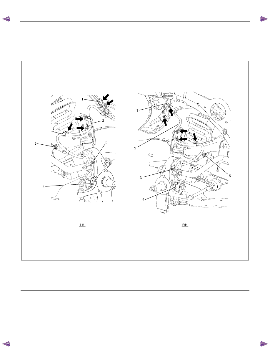
××××2 High Ride Suspension, 4××××4 Front Wheel Speed Sensor
N
⋅m (kgf⋅m/lb⋅ft)
RTW55ALF000101

5B-6 ANTI-LOCK BRAKE SYSTEM
Rear Wheel Speed Sensor
N
⋅m (kgf⋅m/lb⋅ft)
E05R300008
ANTI-LOCK BRAKE SYSTEM 5B-7
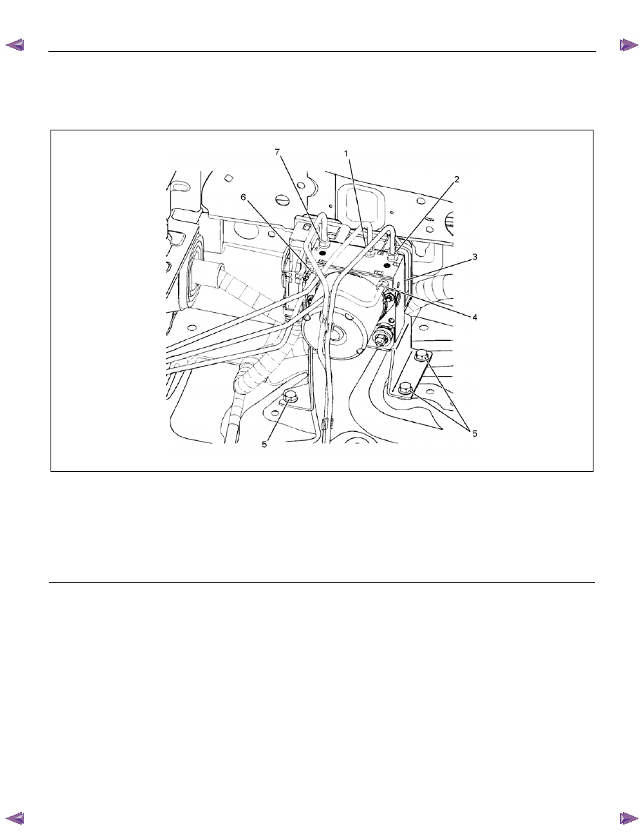
Electronic Hydraulic Control Unit
Electronic Hydraulic Control Unit and Associated Parts
RTW75BMF000301
Legend
(1) Flare Nut to front right wheel cylinder
(2) Flare Nut to front left wheel cylinder
(3) Electronic Hydraulic Control Unit (EHCU)
(4) Flare Nut from master cylinder front
(5)
Bolt
(6) Flare Nut from master cylinder rear
(7) Flare Nut to rear wheel cylinder
Removal
1. Disconnect the harness connector.
2. Loosen five flare nuts and remove brake pipes.
• After disconnecting brake pipe, cap or tape the
openings of the brake pipe to prevent the entry
of foreign matter.
3. Remove three bracket fixing bolts.
Installation
1. Install EHCU and tighten the bolt to the specified
torque.
Torque: 8 N
⋅m (0.8 kgf⋅m /69 lb·in)
2. Tighten the flare nuts to the specified torque.
Torque: 16 N
⋅m (1.6 kgf⋅m /12 lb·ft)
3. Connect the harness connector.
5B-8 ANTI-LOCK BRAKE SYSTEM
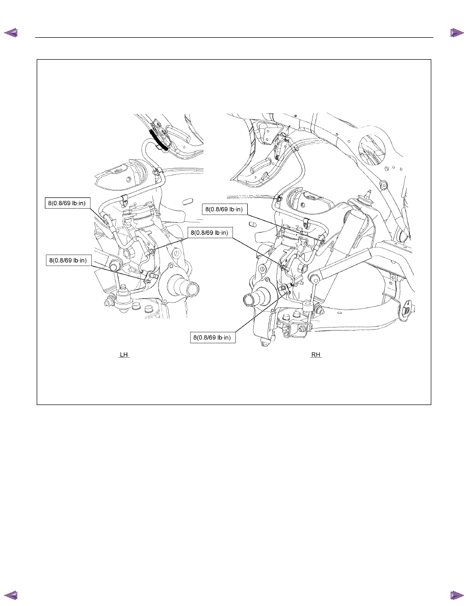
Front Wheel Speed Sensor
Front Wheel Speed Sensor and Associated Parts
4
××××2 (Except High Ride Suspension)
RTW55ALF000401
Legend
(1) Connector Portion
(2) Front Speed Sensor Assembly
(3) Bolt: Cable to Knuckle
(4) Bolt: Sensor to Knuckle
(5) Nut: Cable to Upper Link
Нет комментариевНе стесняйтесь поделиться с нами вашим ценным мнением.
Текст