Isuzu KB P190. Manual — part 721
Engine Mechanical – V6
Page 6A1–107
Page 6A1–107
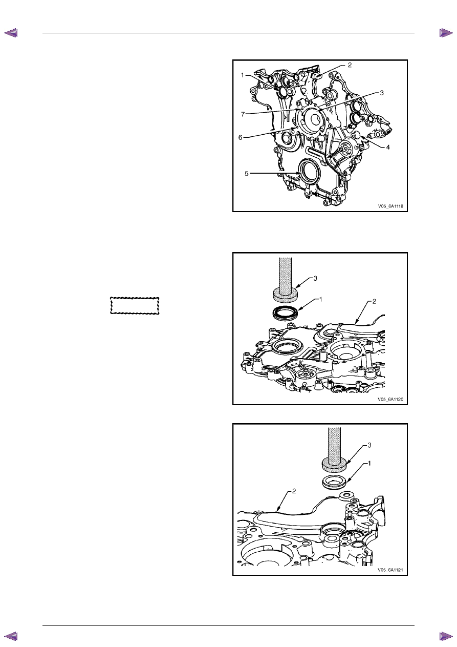
Inspect
1
Inspect both sides of the engine front cover for the
following conditions:
•
damage to the camshaft position actuator valve
oil seal bores (1),
•
damage to the bolt holes (2),
•
damage and/or corrosion to the engine coolant
passage (3),
•
dents or damage to the exterior (4),
•
damage to the crankshaft front oil seal bore (5),
•
gouges or damage to the coolant pump sealing
surfaces (6), and
•
damage to the coolant pump bolt hole
threads (7).
2
Repair or replace the front cover as required.
Figure 6A1 – 90
Reassemble
1
Install a new crankshaft front oil seal (1) into the front
cover (2) using crankshaft front seal installer, Tool
No. J-29184 (3) and a suitable hammer.
CAUTION
Do not lubricate the crankshaft front oil seal
or crankshaft balancer sealing surfaces. The
crankshaft balancer is installed into a dry
seal.
Figure 6A1 – 91
2
Install a new camshaft position actuator valve oil seal
(1) into the front cover (2) using Tool No. EN-46103
(3) and a suitable hammer.
Figure 6A1 – 92
Engine Mechanical – V6
Page 6A1–108
Page 6A1–108
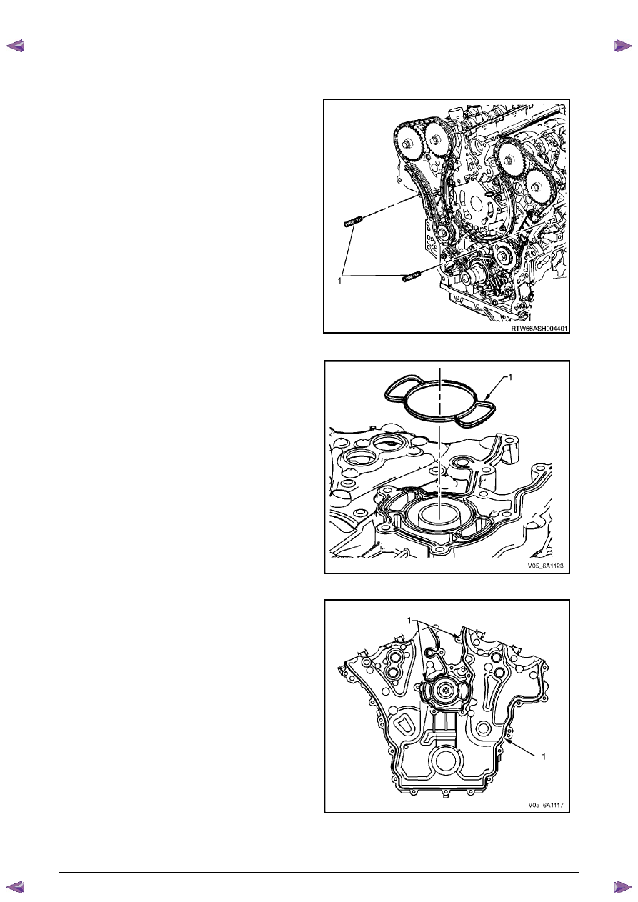
Reinstall
Reinstallation of the front cover is the reverse of the removal procedure, noting the following:
1
Install the guide pins, Tool No. EN-46109 (1) into the
engine block, two places.
Figure 6A1 – 93
2
Install a new engine front cover to cylinder block
seal (1).
Figure 6A1 – 94
3
Apply a 3 mm bead of RTV sealant (1) to the front
cover.
Figure 6A1 – 95
Engine Mechanical – V6
Page 6A1–109
Page 6A1–109
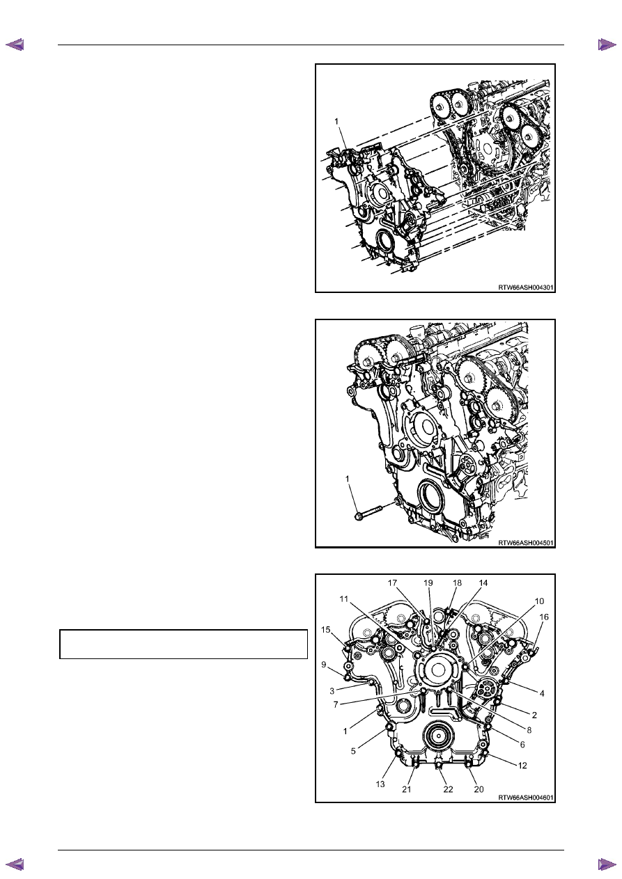
4
Place the front cover onto the special tools and slide
into position.
5
Remove the special tools from the cylinder block.
Figure 6A1 – 96
6
Hand start the front cover bolts (1).
Figure 6A1 – 97
7
Tighten the engine front cover bolts to the correct
torque specification, in the sequence shown.
Engine front cover assembly attaching
bolt torque specification . . . . . . ..20.0 – 26.0 Nm
8
Fill the cooling system, refer to
Section 6B1 Engine
Cooling – V6
.
9
Change the engine oil, refer to
3.1 Engine Oil
.
Figure 6A1 – 98
Engine Mechanical – V6
Page 6A1–110
Page 6A1–110
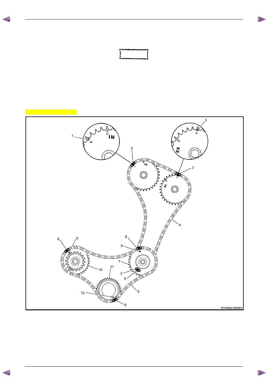
3.16 Timing Chains, Tensioners, Shoes and
Guides
CAUTION
Setting the camshaft timing is required
whenever the camshaft drive system has
been disturbed and the relationship between
any chain and sprocket has been lost. If
required, follow the left-hand secondary
timing chain reinstallation procedure to reset
the camshaft timing.
Primary and Left-hand Secondary Timing Chain Installation
Excluding MY06 Update
Figure 6A1 – 99
Legend
1
Intake Camshaft Sprocket Timing Mark – Left-hand
2
Secondary Timing Chain Bright Plated Link – Left-hand
3
Exhaust Camshaft Sprocket Timing Mark – Left-hand
4
Secondary Timing Chain – Left-hand
5
Primary Timing Chain
6
Camshaft Intermediate Sprocket Timing Mark – Left-hand
7
Camshaft Intermediate Sprocket – Left-hand
8
Primary Timing Chain Bright Plated Link
9
Camshaft Intermediate Sprocket Timing Mark – Right-hand
10
Camshaft Intermediate Sprocket – Right-hand
11
Crankshaft Sprocket
12
Crankshaft Sprocket Timing Mark
Нет комментариевНе стесняйтесь поделиться с нами вашим ценным мнением.
Текст