Isuzu KB P190. Manual — part 1161

7B1-38 MANUAL TRANSMISSION
Inspection and Repair
Make the necessary adjustments, repairs, and part
replacements if excessive wear or damage is
discovered during inspection.
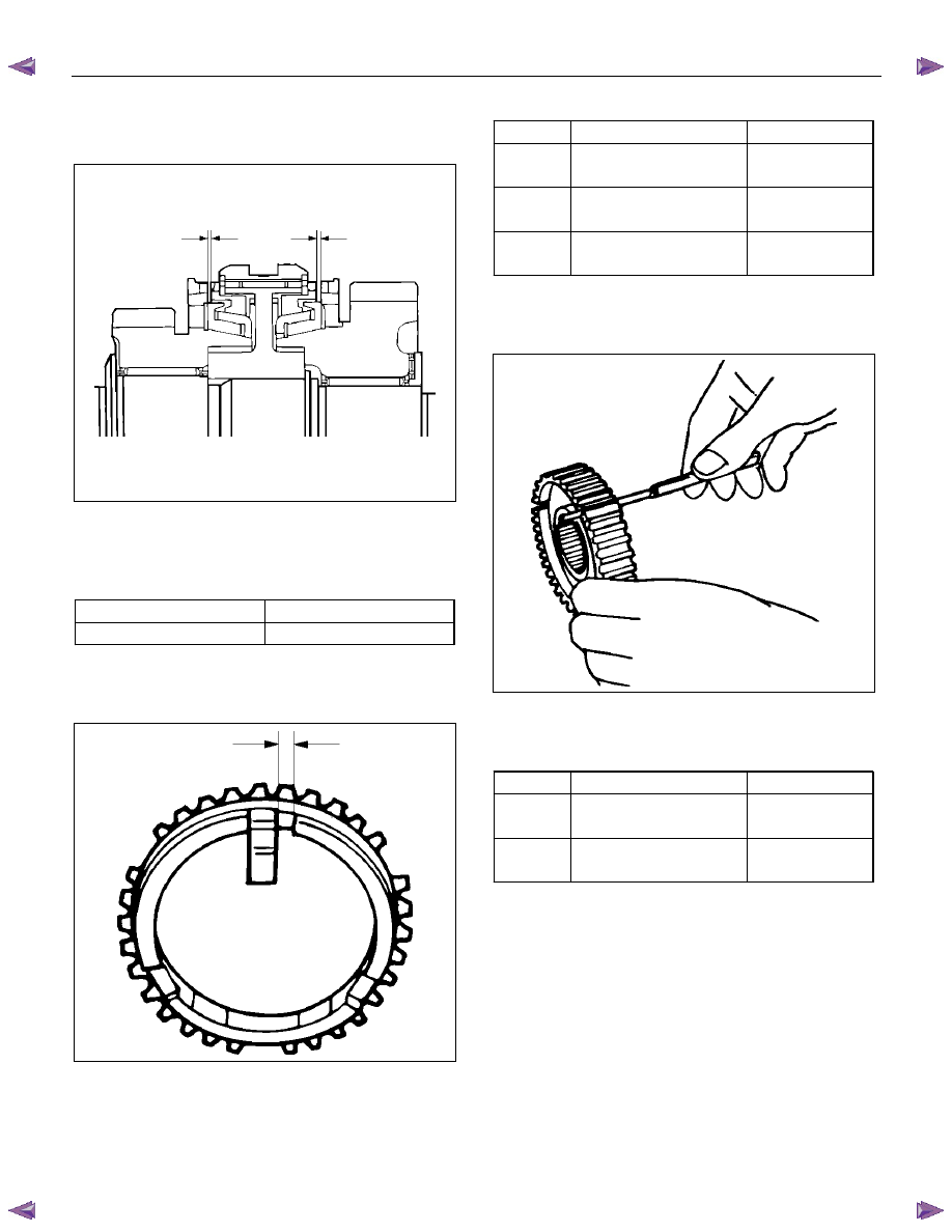
Block Ring and Dog Teeth Clearance
• Use a thickness gauge to measure the clearance
between the block ring and the dog teeth.
226RS035
If the measured value exceeds the specified limit,
the block ring must be replaced.
Block Ring and Dog Teeth Clearance
Standard Limit
1.5 mm (0.059 in)
0.8 mm (0.031 in)
MANUAL TRANSMISSION 7B1-39
1st-2nd Synchronizer (3-CONE)
• Use a thickness gauge to measure the clearance
between the block ring and the dog teeth.
226RS036
If the measured value exceeds the specified limit,
the 1st-2nd synchronizer assembly must be
replaced.
Block Ring and Dog Teeth Clearance
Standard Limit
1.5 mm (0.059 in)
0.8 mm (0.031 in)
Block Ring and Insert Clearance
• Use a vernier caliper or thickness gauge to measure
the clearance between the block ring and the insert.
226RS037
If the measured value exceeds the specified limit,
the block ring and the insert must be replaced.
Block and Insert Clearance
Standard Limit
3rd-4th
3.46 - 3.76 mm
(0.136 - 0.148 in)
4.0 mm
(0.157 in)
1st-2nd
3.86 – 4.16 mm
(0.152 - 0.164 in)
4.9 mm
(0.193 in)
Rev.5th
3.59 - 3.91 mm
(0.141 - 0.154 in)
4.1 mm
(0.161 in)
Clutch Hub and Insert Clearance
• Use a thickness gauge to measure the clearance
between the clutch hub and the insert.
226RS038
If the measured value exceeds the specified limit,
the clutch hub and the insert must be replaced.
Clutch Hub and Insert Clearance
Standard Limit
1st-2nd
3rd-4th
0.01 – 0.21 mm
(0.0004 - 0.0083 in)
0.3 mm
(0.012 in)
Rev-5th
0.09 – 0.31 mm
(0.0035 - 0.0122 in)
0.4 mm
(0.016 in)
7B1-40 MANUAL TRANSMISSION
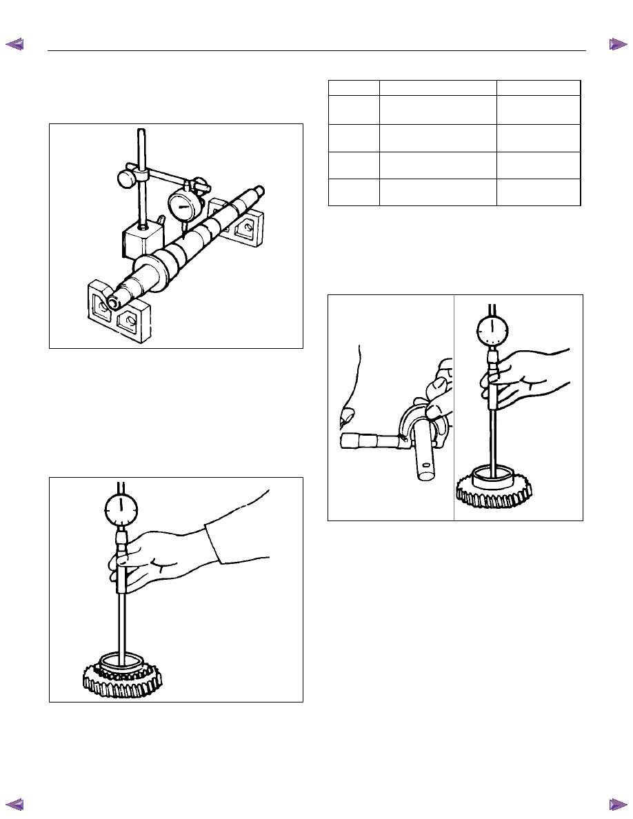
Mainshaft Run-out
• Install the mainshaft to V-blocks.
• Use a dial indicator to measure the mainshaft
central portion run-out.
226RS039
If the measured mainshaft run-out exceeds the
specified limit, the mainshaft must be replaced.
Mainshaft Run-out
Limit: 0.05 mm (0.0020 in)
Gear Inside Diameter
• Use an inside dial indicator to measure the gear
inside diameter.
226RS040
If the measured value is less than the specified limit,
the gear must be replaced.
Gear Inside Diameter
Standard Limit
1st
3rd
45.000 - 45.013 mm
(1.771 - 1.772 in)
45.100 mm
(1.776 in)
2nd
52.000 - 52.013 mm
(2.047 - 2.048 in)
52.100 mm
(2.051 in)
Rev.
48.000 - 48.013 mm
(1.889 - 1.890 in)
48.100 mm
(1.894 in)
5th
32.000 - 32.013 mm
(1.259 - 1.260 in)
32.100 mm
(1.246 in)
Reverse Idler Gear and Idler Gear Shaft
Clearance
• Use a micrometer to measure the idler gear shaft
diameter.
• Use an inside dial indicator to measure the idler
gear inside diameter.
226RS041
• Calculate the idler gear and idler gear shaft
clearance.
Idler gear inside diameter-idler gear shaft diameter =
idle gear and idler gear shaft clearance.
If the measured value exceeds the specified limit,
the idle gear and/or the idler gear shaft must be
replaced
Idler Gear and Idler Gear Shaft Clearance
Standard: 0.041 - 0.074 mm (0.0016 -0.0029 in)
Limit: 0.150 mm (0.0059 in)
MANUAL TRANSMISSION 7B1-41
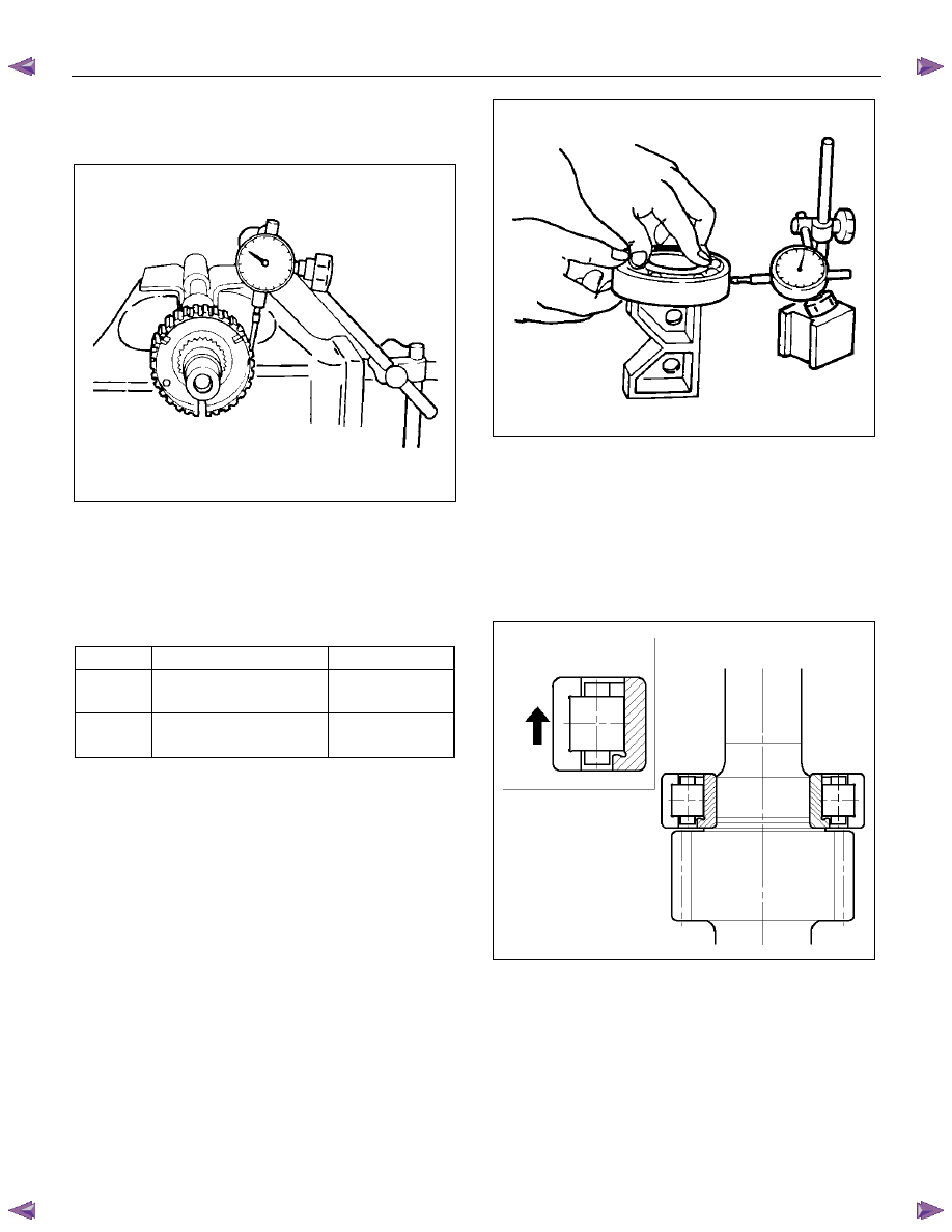
Clutch Hub Spline Play
• Set a dial indicator to the clutch hub which requires
measuring.
226RS042
• Move the clutch hub as far to the right and left as
possible.
Note the dial indicator reading.
If the measured value exceeds the specified limit,
the clutch hub must be replaced.
Clutch Hub Spline Play
Standard Limit
1st-2nd
3rd-4th
0 - 0.1 mm
(0 - 0.004 in)
0.2 mm
(0.008 in)
Rev. 5th
0 - 0.2 mm
(0 - 0.008 in)
0.3 mm
(0.012 in)
Ball Bearing Play
• Use a dial indicator to measure the ball bearing play.
Ball Bearing Play
Limit: 0.2 mm (0.008 in)
226RS043
Reassembly
1. Install the center roller bearing to counter gear shaft.
• Apply engine oil to the bearing inner and outer
circumferences.
• Install the roller bearing in the proper direction.
NOTE: Check that the outer race moves only in the
direction of the arrow.
226RS044
2. Install the front roller bearing by performing the
following steps.
• Use bearing installer 5-8840-2194-0 to install the
front roller bearing inner race to the counter gear
shaft.
• Install the outer race and roller assembly.
The snap ring groove must be facing the
transmission front side.
Нет комментариевНе стесняйтесь поделиться с нами вашим ценным мнением.
Текст