Isuzu KB P190. Manual — part 1159
7B1-30 MANUAL TRANSMISSION
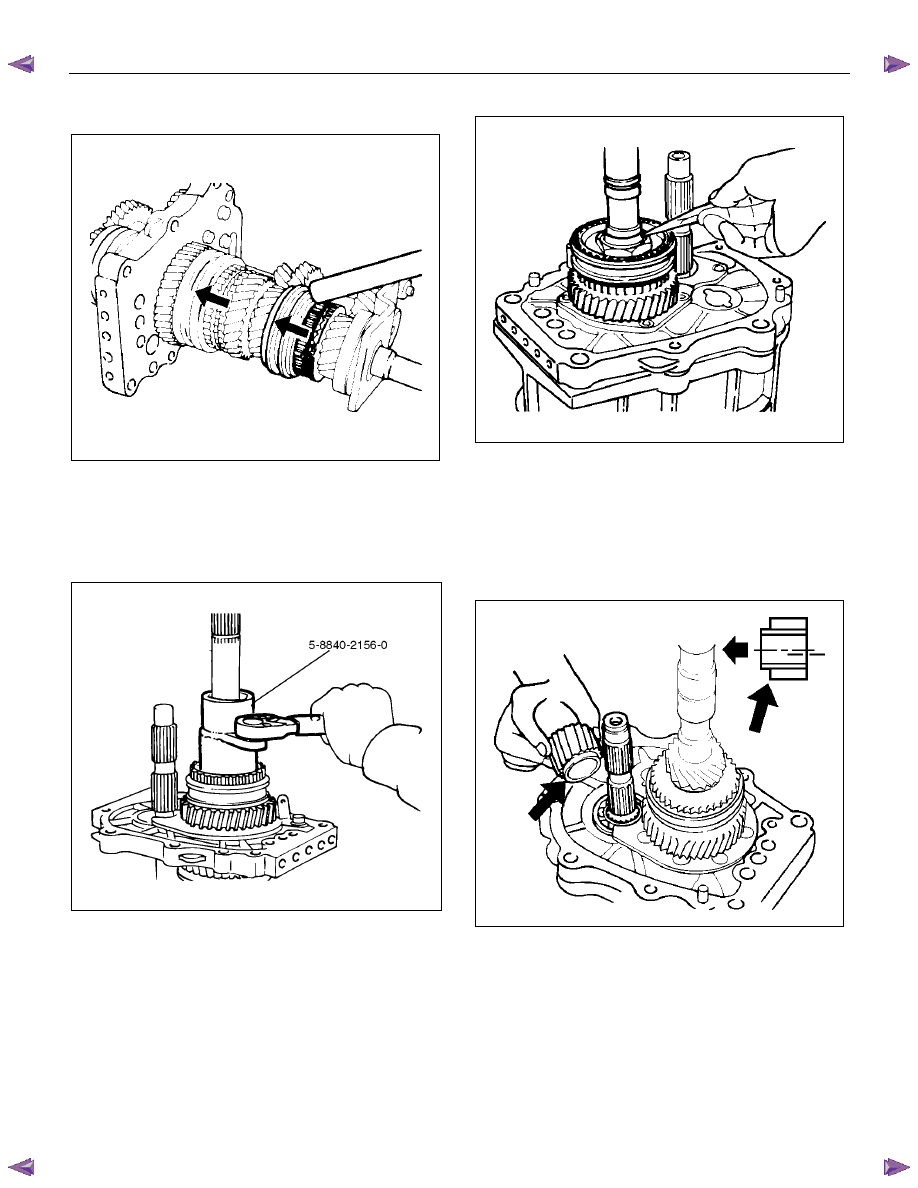
6. Mesh the 1st-2nd and 3rd-4th synchronizers with
both the 1st and 3rd gears (double engagement).
226RS015
This will prevent the mainshaft from turning.
7. Install the new mainshaft hub nut.
Use the mainshaft nut wrench 5-8840-2156-0 to
tighten the mainshaft nut to the specified torque.
Torque: 137 N
⋅⋅⋅⋅m (14.0 kgf⋅⋅⋅⋅m/101 lb⋅⋅⋅⋅ft)
226RW214
8. Use a punch to stake the mainshaft nut.
226RW153
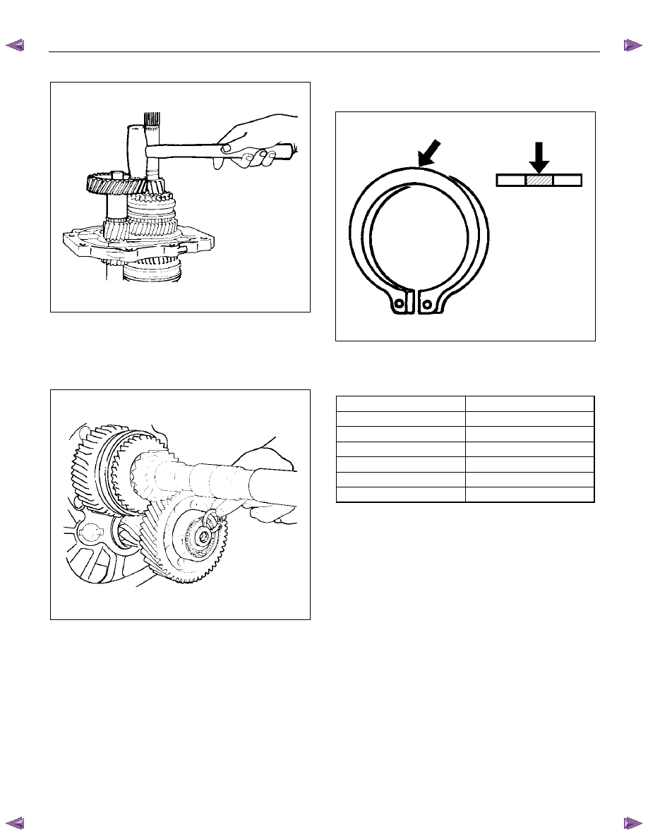
9. Install the needle bearing, 5th block ring, and 5th
gear.
10. Apply engine oil to the counter reverse gear and the
reverse gear.
Install the counter reverse gear to the counter shaft.
The reverse gear projection must be facing the
intermediate plate.
226RW151
MANUAL TRANSMISSION 7B1-31
11. Install the counter 5th gear to the counter shaft.
226RS019
12. Install the ball bearing and bearing snap ring by
performing the following steps:
• Select the snap ring which will provide the
minimum clearance between the ball bearing
and the snap ring.
226RS020
• There are six snap ring sizes available.
The snap rings are color‐coded to indicate
their thickness.
226RS021
Ball Bearing and Snap Ring Clearance
Standard: 0 - 0.15 mm (0 - 0.0059 in)
Snap Ring Availability
Thickness Color
Coding
1.1 mm (0.043 in)
White
1.2 mm (0.047 in)
Yellow
1.3 mm (0.051 in)
Blue
1.4 mm (0.055 in)
Pink
1.5 mm (0.059 in)
Green
1.6 mm (0.063 in)
Brown
• Use a pair of snap ring pliers to install the snap
ring to the counter gear shaft.
The snap ring must be fully inserted into the
counter gear shaft snap ring groove.
13. Assemble the reverse idler shaft, reverse idler gear,
thrust washer, and idle shaft pin into the reverse
idler gear assembly.
The thrust washer should be assembled with the oil
groove faces to gear side.
7B1-32 MANUAL TRANSMISSION
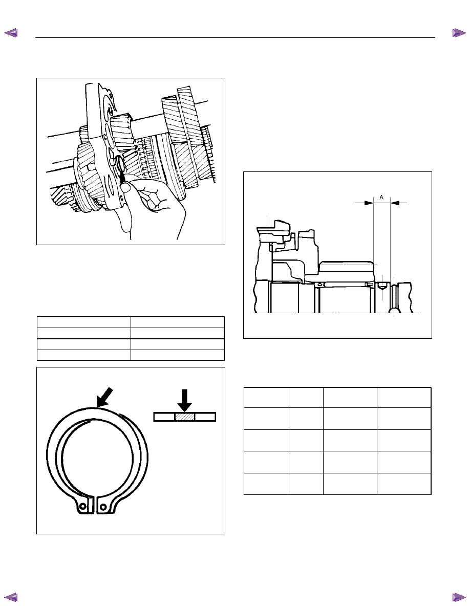
14. Select the reverse idler gear snap ring which will
provide the minimum clearance between the
intermediate plate and the snap ring.
226RS022
• There are three snap ring sizes available.
The snap rings are color-coded to indicate their
thickness.
Intermediate Plate and Snap Ring Clearance
Standard: 0 - 0.15 mm (0 - 0.0059 in)
Snap Ring Availability
Thickness Color
Coding
1.2 mm (0.047 in)
White
1.3 mm (0.051 in)
Yellow
1.4 mm (0.055 in)
Blue
226RS021
• Use a pair of snap ring pliers to install the snap
ring to the reverse idler shaft.
The snap ring must be fully inserted into the
reverse idler shaft snap ring groove.
15. Install the thrust washer and lock ball by performing
the following steps:
• Use a thickness gauge to measure the
clearance between the 5th gear and the thrust
washer.
5th Gear and Thrust Washer Clearance
Standard: 0.10 - 0.25 mm (0.004 - 0.010 in)
• Measure clearance "A" as shown in the figure.
226RS023
• Select an appropriate thrust washer from the
chart.
• There are four thrust washer sizes available.
Thrust Washer Availability
Thickness
mm (in)
Color
Coding
A mm (in)
Clearance
mm (in)
7.9 (0.311)
White
8.05 - 8.1
(0.317-0.319)
0.15 - 0.25
(0.006-0.010)
8.0 (0.315)
Yellow
8.1 - 8.2
(0.319-0.323)
0.1 - 0.25
(0.004-0.010)
8.1 (0.319)
Green
8.2 - 8.3
(0.323-0.327)
0.1 - 0.25
(0.004-0.010)
8.2 (0.323)
Blue
8.3 - 8.36
(0.327-0.329)
0.1 - 0.21
(0.004-0.008)
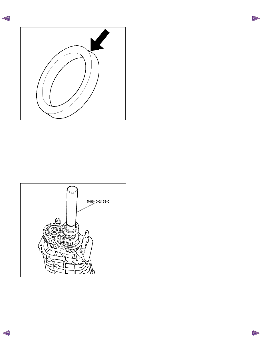
• The thrust washers are color-coded to indicate
their thickness, as shown in the figure.
MANUAL TRANSMISSION 7B1-33
226RS024
• Apply grease to the thrust washer and the lock
ball.
• Install the thrust washer and the lock ball.
16. Install the thrust plate and retainer.
17. Install the retainer snap ring, clip, speedometer drive
gear and bearing snap ring.
18. Apply engine oil to the bearing inner and outer
circumference.
Use the installer 5-8840-2159-0 to install the ball
bearing to the mainshaft.
226L100002
19. Install the bearing snap ring.
Нет комментариевНе стесняйтесь поделиться с нами вашим ценным мнением.
Текст