Isuzu KB P190. Manual — part 26
1-70 HEATER AND AIR CONDITIONING
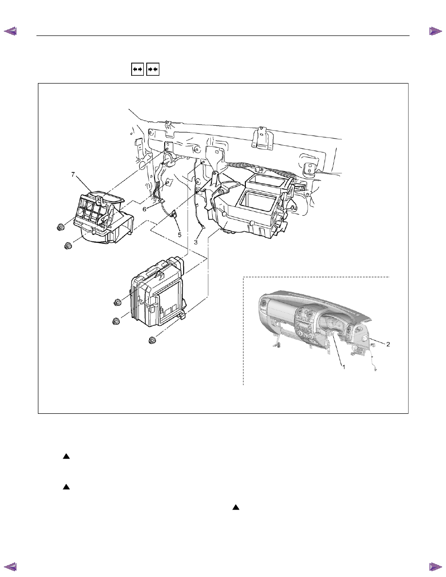
BLOWER UNIT ASSEMBLY
REMOVAL AND INSTALLATION
This illustration is based on RHD model
RTW710LF001801
Removal Steps
1. Control cable
2. Instrument panel assembly and cross
beam
3. Electronic thermostat connector
4. Evaporator or duct
5. Resistor connector
6. Blower motor connector
7. Blower unit assembly or intake box
assembly
Installation Steps
7. Blower unit assembly or intake box
assembly
6. Blower motor connector
5. Resistor connector
4. Evaporator or duct
3. Electronic thermostat connector
2. Instrument panel assembly and cross
beam
1. Control cable

HEATER AND AIR CONDITIONING 1-71
Important Operations - Removal
2. Instrument Panel Assembly and Cross Beam
Refer to SECTION 10 “INSTRUMENT PANEL”.
4. Evaporator or Duct
Refer to “EVAPORATOR” or “DUCT” in this section.
Important Operation - Installation
2. Instrument Panel Assembly and Cross Beam
Adjust the heater control cables.
Refer to “CONTOROL LEVER ASSEMBLY” in this section.
1-72 HEATER AND AIR CONDITIONING
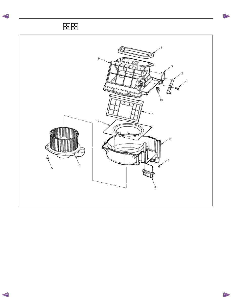
DISASSEMBLY AND REASSEMBLY
This illustration is based on RHD model
Disassembly Steps
1. Attaching screw
2. Intake link
3. Intake lever
4. Intake packing
5. Attaching screws
6. Blower motor assembly
7. Attaching screw
8. Flat resistor
9. Upper case
10. Lower case
11. Mode door
12. Bell mouth
13. Control cable clamp
Reassembly Steps
13. Control cable clamp
12. Bell mouth
11. Mode door
10. Lower case
9. Upper case
8. Flat resistor
7. Attaching screw
6. Blower motor assembly
5. Attaching screws
4. Intake packing
3. Intake lever
2. Intake link
1. Attaching screw
HEATER AND AIR CONDITIONING 1-73
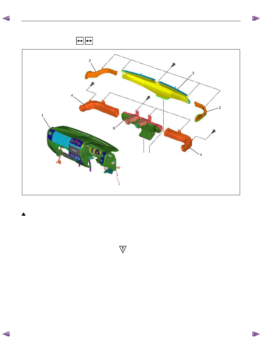
DEFROSTER NOZZLE AND VENT DUCT
REMOVAL AND INSTALLATION
This illustration is based on RHD model
RTW710MF000201
Removal Steps
1. Instrument panel assembly and cross beam
2. Side def hose RH/LH
3. Defroster nozzle
4. Vent duct driver side and assist side
5. Center vent duct
Installation Steps
5. Center vent duct
4. Vent duct driver side and assist side
3. Defroster nozzle
2. Side def hose RH/LH
1. Instrument panel assembly and cross beam
Important Operation - Removal
1. Instrument Panel Assembly and Cross Beam
Refer to SECTION 10 “INSTRUMENT PANEL”.
Нет комментариевНе стесняйтесь поделиться с нами вашим ценным мнением.
Текст