Isuzu KB P190. Manual — part 27
1-74 HEATER AND AIR CONDITIONING
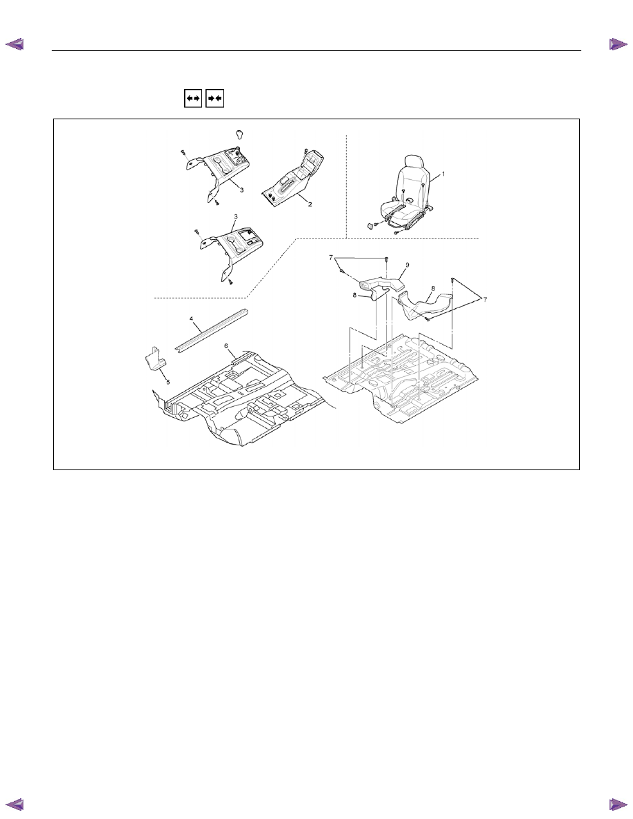
REAR HEATER DUCT
REMOVAL AND INSTALLATION
This illustration is based on RHD model
RTW710LF004301
Disassembly Steps
1. Front seat assembly (RH/LH)
• Refer to SECTION 10 “FRONT
SEAT”.
2. Rear floor console
• Refer to SECTION 10 “FLOOR
CONSOLE”.
3. Front floor console (A/T, M/T Model)
• Refer to SECTION 10 “FLOOR
CONSOLE”.
4. Sill plate (RH/LH)
• Refer to SECTION 10 “INTERIOR
TRIM PANELS”.
5. Dash side trim cover (RH/LH)
6. Carpet
7.
Clip
8. Rear Heater duct (RH/LH)
9. Rear Heater duct center
Reassembly Steps
9. Rear heater duct center
8. Rear heater duct (RH/LH)
7.
Clip
6.
Carpet
5. Dash side trim cover (RH/LH)
4. Sill plate (RH/LH)
• Refer to SECTION 10 “INTERIOR
TRIM PANELS”.
3. Front floor console (A/T, M/T Model)
• Refer to SECTION 10 “FLOOR
CONSOLE”.
2. Rear floor console
• Refer to SECTION 10 “FLOOR
CONSOLE”.
1. Front seat assembly (RH/LH)
• Refer to SECTION 10 “FRONT
SEAT”.
HEATER AND AIR CONDITIONING 1-75
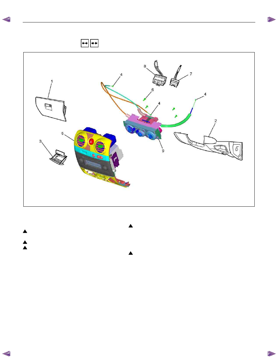
CONTROL LEVER ASSEMBLY
REMOVAL AND INSTALLATION
This illustration is based on RHD model
RTW710MF000801
Removal Steps
1. Glove box
2. Instrument panel driver side lower cover
3.
Ash-tray
4. Control cables
5. Center cluster
6. Attaching screw
7. A/C switch connector
8. Fan switch connector
9. Control lever assembly
Installation Steps
9. Control lever assembly
8. Fan switch connector
7. A/C switch connector
6. Attaching screw
5. Center cluster
4. Control cables
3.
Ash-tray
2. Instrument panel driver side lower cover
1. Glove box

1-76 HEATER AND AIR CONDITIONING
Important Operations - Removal
2. Instrument Panel Driver Lower Cover
Refer to SECTION 10 “INSTRUMENT PANEL” .
RTW710SH000601
4. Control Cables
Disconnect control cables at each side of the unit.
5. Center Cluster
Refer to SECTION 10 “INSTRUMENT PANEL”.
HEATER AND AIR CONDITIONING 1-77
Important Operations - Installation
9. Control Lever Assembly
Air source control cable
RHD
1) Slide the control lever to the left (“CIRC” position).
2) Connect the control cable at the "CIRC" position of the link
unit of blower assembly and fix it with the clip.
LHD
1) Slide the control lever to the right (“FRESH” position).
2) Connect the control cable at the "FRESH" position of the
link unit of blower assembly and fix it with the clip.
Temperature control cable
RHD
1) Turn the control knob to the right (“FULL HOT” position).
2) Connect the control cable at the “FULL HOT” position of the
mix lever of the heater unit and fix it with the clip.
LHD
1) Turn the control knob to the left (“FULL COLD” position).
2) Connect the control cable at the “FULL COLD” position of
the mix lever of the heater unit and fix it with the clip.
Air select control cable
RHD
1) Turn the control knob to the left (“VENT” position).
2) Connect the control cable at the “VENT” position of the
mode control link of the heater unit and fix it with the clip.
LHD
1) Turn the control knob to the right (“DEF” position).
2) Connect the control cable at the “DEF” position of the mode
control link of the heater unit and fix it with the clip.
4. Control Cables
Check control cable operation
Нет комментариевНе стесняйтесь поделиться с нами вашим ценным мнением.
Текст