Isuzu KB P190. Manual — part 678
Engine Mechanical – V6
Page 6A1–233
Crankshaft Final Installation Procedure
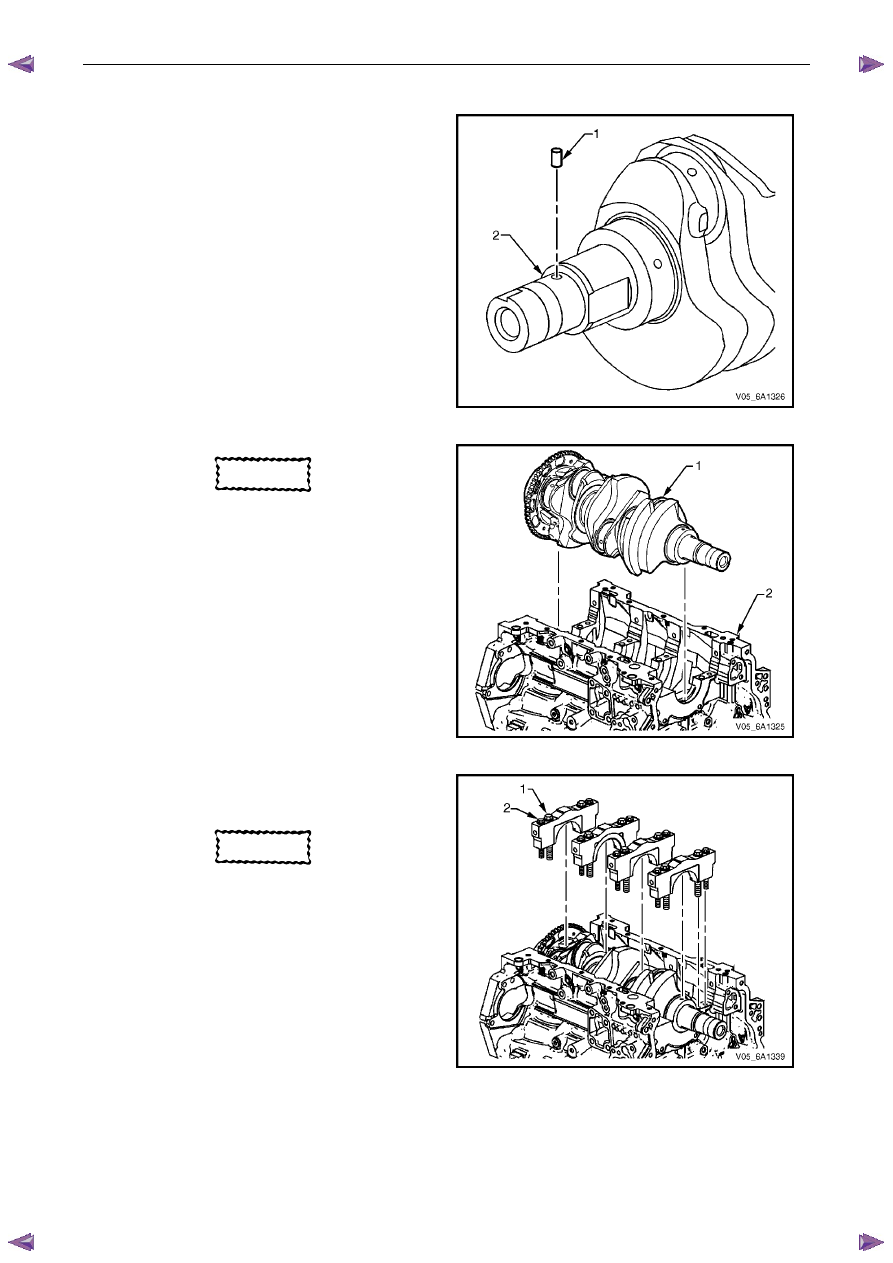
1
If removed, install the crankshaft sprocket drive
pin (1). Lightly tap the pin in place with a small soft
face, bronze/plastic, hammer until it bottoms in the
hole.
Figure 6A1 – 432
CAUTION
Ensure the crankshaft position sensor has
been removed from the cylinder block prior
to loading the crankshaft, as damage to the
sensor may occur.
2
Apply a liberal amount of clean engine oil to the upper
and lower bearing surfaces.
3
Gently lower the crankshaft (1) into position in the
cylinder block (2).
Figure 6A1 – 433
4
Install the crankshaft main bearing caps.
5
Loosely install the original inner main cap bolts (1).
CAUTION
The outer crankshaft bearing cap bolts (2)
are yield tightened during assembly and
must be replaced prior to reassembly. Outer
crankshaft bearing cap bolts that are not
replaced will not torque to the correct clamp
load and can lead to serious engine damage.
6
Loosely install the new outer main bearing cap
bolts (2).
7
Gently tap the crankshaft main bearing caps with a
soft-faced hammer to help seat the caps.
Figure 6A1 – 434

Engine Mechanical – V6
Page 6A1–234
8
Loosely install new short / inner side main cap
bolts (4).
CAUTION
• The short / inner side main cap bolts
originally have a sealant on the flange of
the bolt head. New bolts must be used. If
new bolts are not used, oil can leak from
the crankcase past the bolts.
• The long / outer side main cap bolts
originally have a sealant on the flange of
the bolt head. New bolts must be used. If
new bolts are not used, oil can leak from
the crankcase past the bolts.
9
Loosely install the new long / outer side main cap
bolts (3).
10
Tighten the main caps bolts to the correct torque
specification, and in the following sequence.
Crankshaft main bearing cap inboard
attaching bolt torque specification:
Stage 1 . . . . . . .20.0 Nm
Stage
2 . . . . . . . . .80°
Crankshaft main bearing cap outboard
attaching bolt torque specification:
Stage 1 . . . . . . .15.0 Nm
Stage
2 . . . . . . . ...110°
Crankshaft main bearing cap side
attaching bolt torque specification:
Stage 1 . . . . . . .30.0 Nm
Stage
2 . . . . . . . . .60°
Figure 6A1 – 435
11
Ensure the crankshaft turns without binding or noise.
12
Install the remaining components in the reverse order to removal, refer to the appropriate Section.
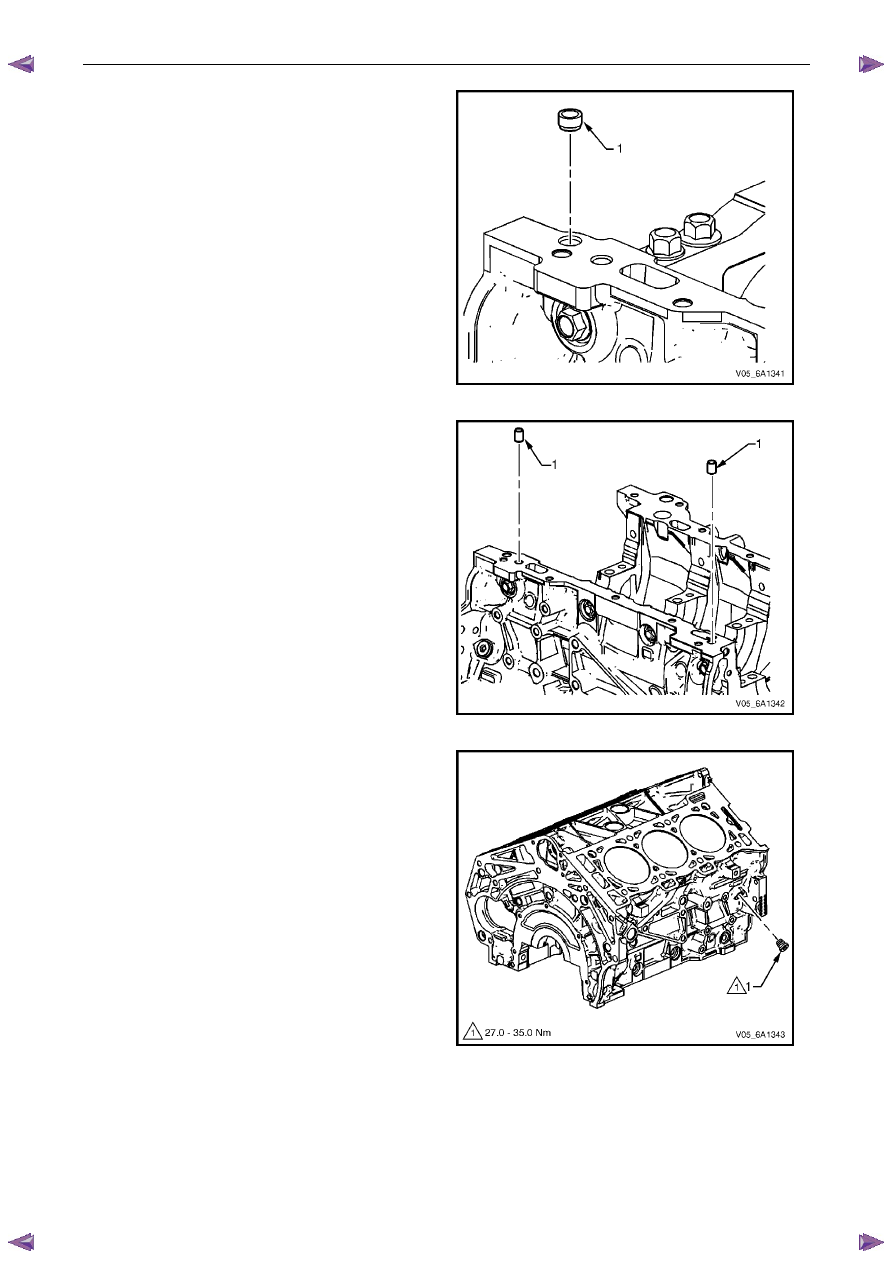
4.7 Cylinder
Block
Disassemble
1
Remove oil jet bolt (1) attaching the oil jet (2), three
places.
Figure 6A1 – 436
Engine Mechanical – V6
Page 6A1–235
2
Remove the right-hand front oil pan rail oil gallery
expansion plug (1).
Figure 6A1 – 437
3
Remove the cylinder block-to-oil pan alignment
dowels (1).
Figure 6A1 – 438
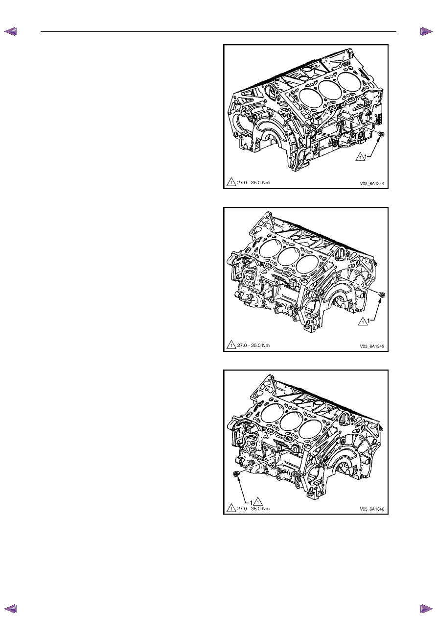
4
Remove the right-hand side M14 oil gallery threaded
plug (1).
Figure 6A1 – 439
Engine Mechanical – V6
Page 6A1–236
5
Remove the right-hand side M14 coolant drain
threaded plug (1).
Figure 6A1 – 440
6
Remove the rear M14 oil gallery threaded plug (1).
Figure 6A1 – 441
7
Remove the left-hand side M14 coolant drain
threaded plug (1).
Figure 6A1 – 442
Нет комментариевНе стесняйтесь поделиться с нами вашим ценным мнением.
Текст