Isuzu KB P190. Manual — part 679
Engine Mechanical – V6
Page 6A1–237
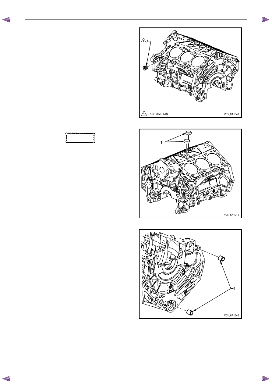
8
Remove the left-hand side M20 oil gallery threaded
plug (1).
Figure 6A1 – 443
CAUTION
Do not force coolant expansion plugs
downwards during removal procedure as the
cylinder block will be damaged.
9
Remove the coolant expansion plugs (1).
Figure 6A1 – 444
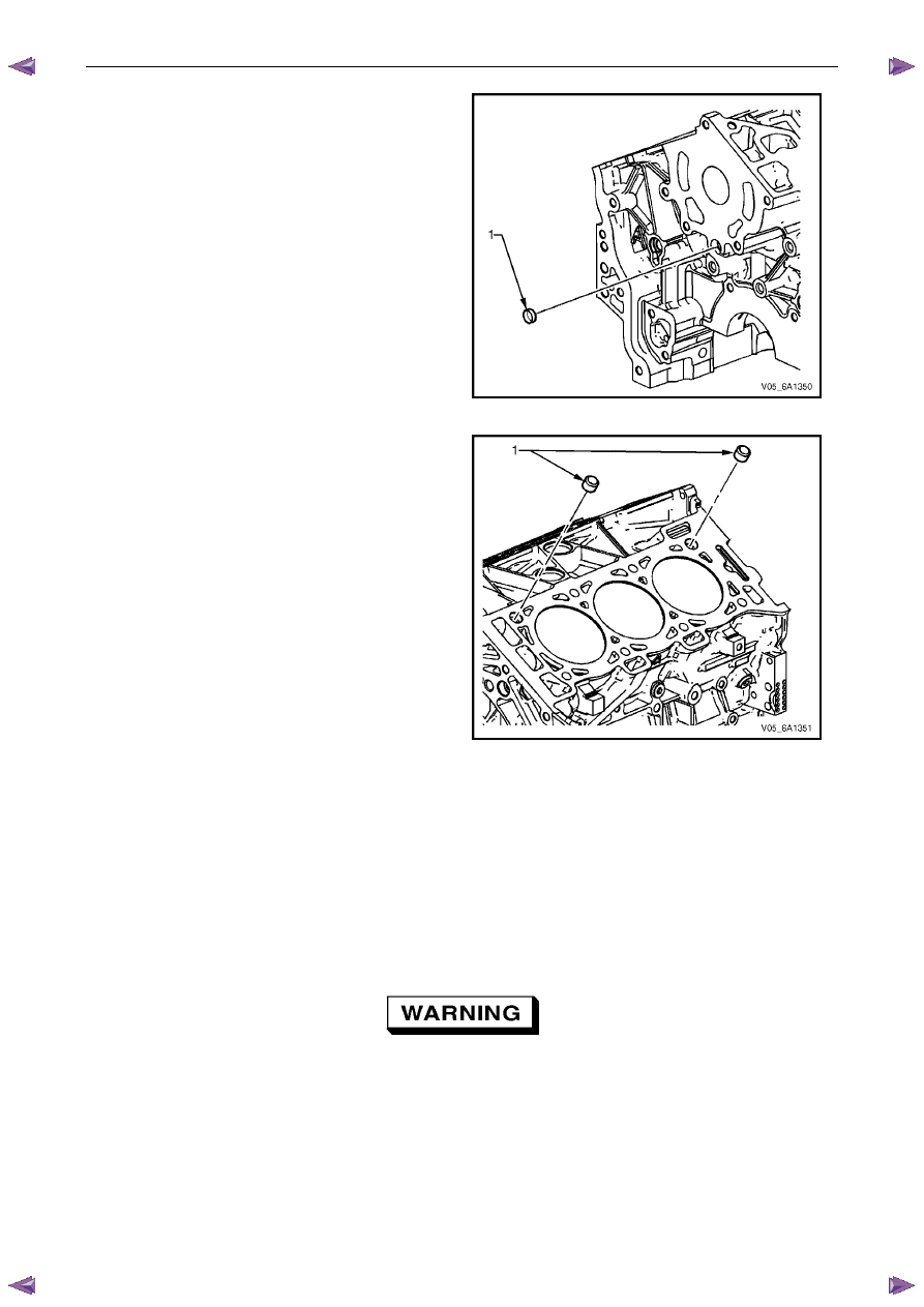
10
Remove the cylinder block-to-transmission alignment
dowels (1).
Figure 6A1 – 445
Engine Mechanical – V6
Page 6A1–238
11
Remove the front oil gallery expansion plug (1).
Figure 6A1 – 446
12
Remove the cylinder block-to-cylinder head alignment
dowels (1).
Figure 6A1 – 447
Clean
1
Remove all thread sealant, gasket material or sealant using a commercially available plastic or wood scraper.
2
Clean all the following areas with a suitable solvent:
•
sealing surfaces,
•
cooling passages,
•
oil passages, and
•
bearing journals.
3
Clean all threaded and through holes with a suitable solvent.
Safety glasses must be worn when using
compressed air.
4
Dry the engine block with compressed air.
Engine Mechanical – V6
Page 6A1–239
Inspect
Visual Inspection
N O T E
The following procedure assumes the engine has
been disassembled and cleaned, as described
above.
1
Inspect the crankshaft bearing journals for damage or spun bearings. The crankshaft bearing journals are not
repairable and if damage is found, the cylinder block assembly must be replaced.
2
Inspect the primary camshaft chain tensioner mounting surface on the engine block for burrs or any defects that
would affect the sealing of the new primary camshaft chain tensioner gasket.
3
Inspect all sealing and mating surfaces for damage, repair or replace the cylinder block assembly if required.
4
Inspect all threaded and through holes for damage or excessive debris.
5
Inspect all bolts for damage, if damaged replace with new bolts only.
6
Inspect the cylinder walls for cracks or damage. The cylinder sleeves are not serviced separately, if the cylinders
are damaged the cylinder block assembly must be replaced.
7
Inspect the engine block for cracks. Do not repair any cracks. If cracks are found, the cylinder block assembly must
be replaced. Repair any damaged threaded holes, refer to 4.9
Thread Repair Specifications.
Measuring Cylinder Bore Diameter
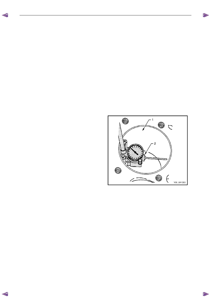
1
Measure the cylinder bore diameter 37 mm from the
deck face (1) using a commercially available bore
gauge or Tool No. J-8087 (2).
2
Record the results and compare with the dimensions
listed in the specifications, refer to 5
Specifications.
N O T E
If the cylinder diameter exceeds the
specifications, the cylinder block may be
oversized to 0.25 mm. Only one size of
oversized pistons and rings are available for
service. If the cylinder bore diameter exceeds
specification by more than 0.25 mm, the
cylinder block must be replaced.
Figure 6A1 – 448
Measuring Cylinder Bore Taper
1
Measure the cylinder bore along the thrust surfaces, perpendicular to the crankshaft centreline, at 10 mm below the
deck surface and record the measurement.
2
Measure the cylinder bore along the thrust surfaces, perpendicular to the crankshaft centreline, at 100 mm below
the deck surface and record the measurement.
3
Calculate the difference between the two measurements. The result will be the cylinder taper.
4
Compare the results with the dimensions listed in the specifications, refer to 5
Specifications.
N O T E
If the cylinder diameter exceeds the
specifications, the cylinder block may be
oversized to 0.25 mm. Only one size of oversized
pistons and rings are available for service. If the
cylinder bore diameter exceeds specification by
more than 0.25 mm, the cylinder block must be
replaced.
Measuring Cylinder Bore Out-of-Round
1
Measure both the thrust and non-thrust cylinder diameter at 10 mm below the deck. Record your measurements.
Engine Mechanical – V6
Page 6A1–240
2
Calculate the difference between the two measurements. The result will indicate out-of-round at the upper end of
the cylinder.
3
Measure both the thrust and non-thrust cylinder diameter at 100 mm below the deck surface. Record your
measurements.
4
Calculate the difference between the two measurements. The result will indicate out-of-round at the lower end of
the cylinder.
5
Compare your results with the dimensions listed in the specifications, refer to 5
Specifications.
N O T E
If the cylinder diameter exceeds the
specifications, the cylinder block may be
oversized to 0.25 mm. Only one size of oversized
pistons and rings are available for service. If the
cylinder bore diameter exceeds specification by
more than 0.25 mm, the cylinder block must be
replaced.
Deck Flatness Inspection
1
Ensure the engine block decks are clean and free of
gasket material.
2
Inspect the surface for any imperfections or scratches
that could inhibit correct cylinder head gasket sealing.
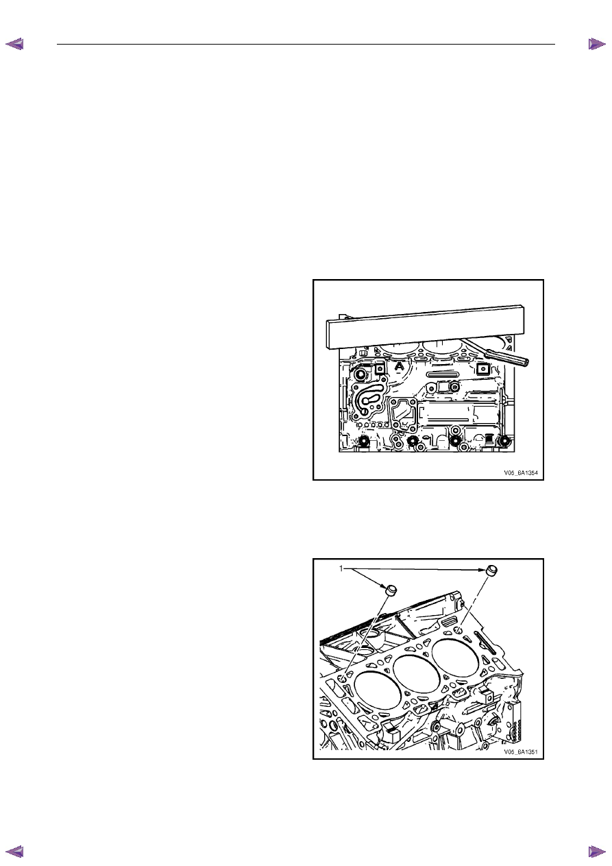
3
Place a straight-edge diagonally across the cylinder
block deck face surface.
4
Measure the clearance between the straight-edge
and the cylinder block deck face using a feeler gauge
at 4 points along the straight-edge.
5
If the warpage is less than 0.05 mm, the cylinder
block deck surface does not require resurfacing.
6
If the warpage is between 0.05 ±0.20 mm or any
imperfections or scratches that could inhibit correct
cylinder head gasket sealing are present, the cylinder
block deck surface requires resurfacing.
7
If resurfacing is required the maximum amount that
can be removed is 0.25 mm.
8
If the cylinder block deck surface requires more than
0.25 mm material removal the block must be
replaced.
Figure 6A1 – 449
Reassemble
1
Install the cylinder block-to-cylinder head alignment
dowels (1).
Figure 6A1 – 450
Нет комментариевНе стесняйтесь поделиться с нами вашим ценным мнением.
Текст