Isuzu KB P190. Manual — part 129
4C1-12 FRONT WHEEL DRIVE
17. Support the differential case by the jack.
18. Remove the front axle mounting bolts and nuts, lower the
jack slowly. Remove the left side drive shaft end from the
knuckle, then lower the axle assembly from the vehicle.
CAUTION :
1. During the work, be sure that the axle assembly is
supported securely.
2. Be careful not to damage the bellows of the power
steering unit by interference.
3. Be careful not to damage the breather pipe and
breather pip bracket of the shift on the fly by
interference.
Installation
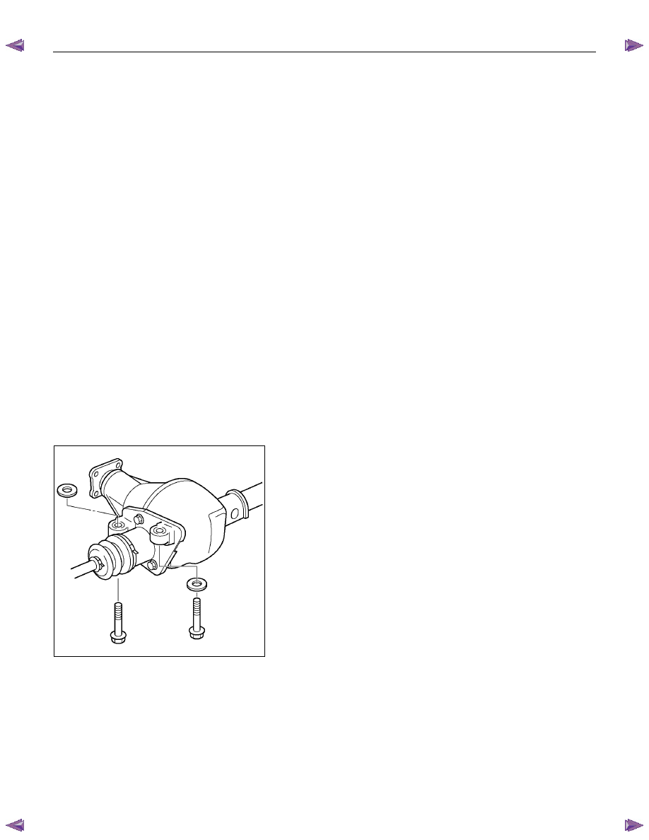
1. Support the differential case by the jack.
2. Jack up the front drive axle assembly, install the left side
drive shaft to the knuckle, then install the mount bolts and
nuts.
CAUTION :
1. Be careful not to damage the bellows of the power
steering unit by interference.
2. Be careful not to damage the breather pipe and
breather pip bracket of the shift on the fly by
interference.
3. When installing the drive shaft to the knuckle, be
careful not to damage the oil seal inside of the knuckle.
RTW34CSH000101
3. Tighten the mounting bolts and nuts to the specified torque.
Torque : 169 N·m (17.2kgf·m/124 lb·ft)
4. Install the right side knuckle with lower control arm to the
upper control arm.
Refer to Knuckle in Suspension section.
CAUTION :
When insert the drive shaft to the knuckle, be careful not
to damage the oil seal inside of the knuckle.
5. Align the bolt hole of the lower control arm, install the bolts
and nuts.
FRONT WHEEL DRIVE 4C1-13
NOTE :
Adjust the buffer clearance before tighten the bolts and nuts of
the lower control arm.
6. Install the breather hose of the front axle.
7. Install the actuator connector of the shift on the fly.
8. Install the tie-rod end of the power steering unit to the
knuckle, tighten the nut to the specified torque.
Torque : 98 N·m (10.0kgf·m/73 lb·ft)
9. Install lower bolts and nuts of the shock absorber, tighten it
to the specified torque.
Torque : 93 N·m (9.5kgf·m/69 lb·ft)
10. Install lower nuts of the stabilizer link, tighten it to the
specified torque.
Torque : 50 N·m (5.1kgf·m/37 lb·ft)
11. Install the suspension crossmember.
12. Install the torsion bar.
Refer to Torsion Bar in Suspension section.
13. Install the front propeller shaft.
Refer to Front Propeller Shaft in this section.
14. Install the hub and disc assembly and adjust the bearing
preload.
Refer to Front Hub and Disc in this section.
15. Install the wheel speed sensor of the antilock brake
system.
16. Install the brake caliper. Tighten the bolt of the caliper
bracket to the specified torque.
Torque : 226 N·m (23.0kgf·m/166 lb·ft)
17. Install the stone guard.
18. Install the tire and wheel.
19. Lower the vehicle, adjust the trim height.
Refer to Trim Height Adjustment in Front Alignment
section.
20. Tighten the bolts and nuts of the lower control arm to the
specified torque.
Refer to Lower Control Arm in Suspension section.
4C1-14 FRONT WHEEL DRIVE
FRONT AXLE DRIVE SHAFT
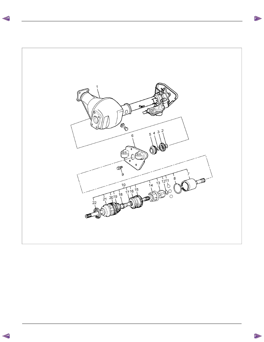
Front Axle Drive Shaft and Associated Parts
RTW34CLF000401
Legend
1. Axle Case and Differential
2. Snap Ring
3.
Bearing
4. Snap Ring
5. Oil Seal
6.
Bracket
7. DOJ Case
8.
Circlip
9.
Bolt
10. Drive shaft Joint Assembly
11.
Ball
12. Snap Ring
13. Ball Retainer
14. Ball Guide
15.
Band
16.
Bellows
17.
Band
18.
Band
19.
Bellows
20.
Band
21. UJ Shaft
22. Dust Seal

FRONT WHEEL DRIVE 4C1-15
Disassembly
NOTE :
For the left side, follow the same steps as right side.
1. Use a hammer and chisel to remove the 3 pawls (above
the large and small boot bands on the DOJ side).
CAUTION :
Take care not to damage the bellows during band removal.
2. Remove band (1).
3. Pry off circlip (1) with a screwdriver or equivalent.
4. Remove drive shaft joint assembly.
5. Remove the six balls (1) with a screwdriver or equivalent.
Нет комментариевНе стесняйтесь поделиться с нами вашим ценным мнением.
Текст